


Chapter 3
3-10
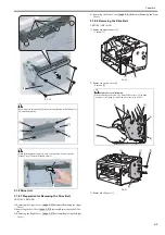
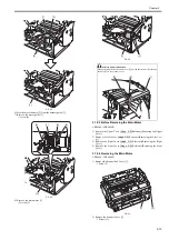
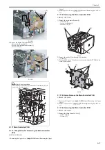
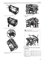
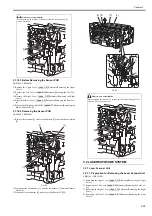
F-3-22
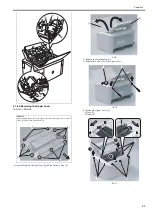
4) Remove the drive belt [1].
F-3-23
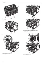
3.1.8.3 Before Removing the Drive Belt
0025-1218
LBP6000 / LBP6000B
Reference[Removing the Upper
Cover]
2) Remove the Left Cover.
Reference[Removing the Left Cov-
er]
3) Remove the Right Cover.
Reference[Removing the Right
Cover]
4) Remove the Front Cover.
Reference[Removing the Front
Cover]
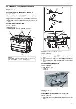
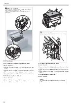
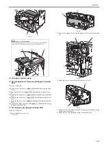
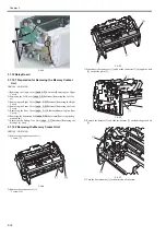
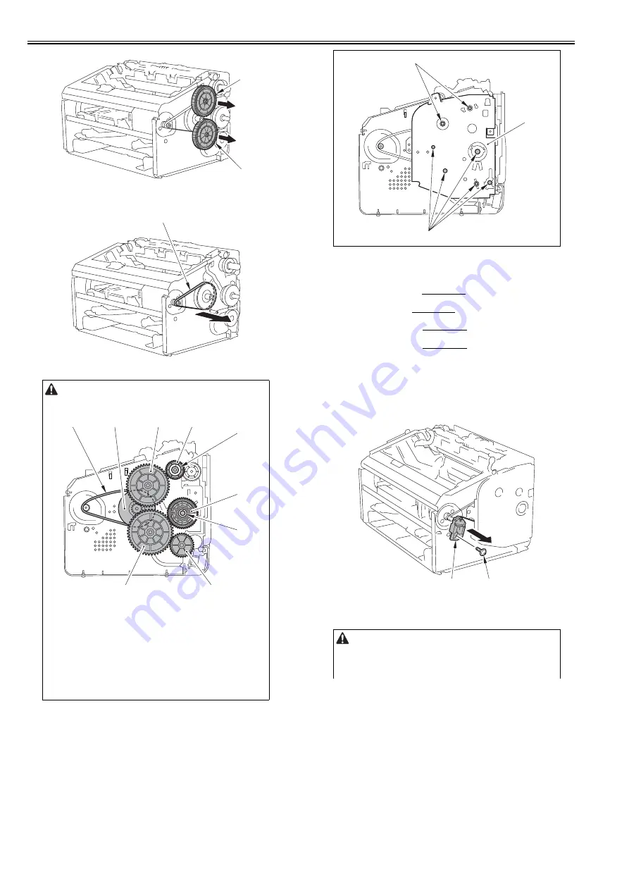
3.1.8.4 Removing the Drive Belt
0025-1220
LBP6000 / LBP6000B
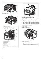
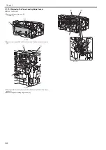
1) Remove the Tension Unit [1].
- 1 Screw [2]
F-3-24
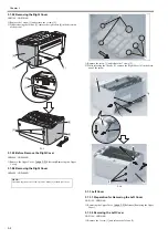
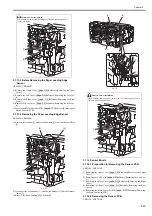
2) Remove the Drive Cover [1].
- 4 Screws [2]
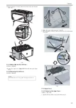
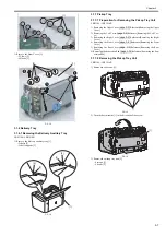
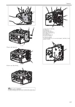
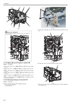
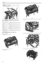
Points to note at installation
- When assembling the drive gears, follow the order as below.
[1] Primary speed down pulley
[2] Timing belt
[3] Fixing ratchet gear
[4] Fixing gear
[5] Cartridge gear
[6] Coupling gear
[7] Delivery speed down W gear
[8] Compression spring
[9] Compression spring
- When attaching the drive gear, align the 7 shaft holes [1] with the drive
cover [2].
[1]
[1]
[1]
[1]
[2]
[3]
[6]
[7]
[9]
[8]
[4]
[5]
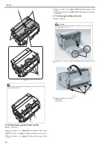
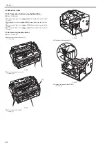
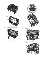
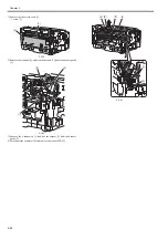
Points to Note at Removing
When removing the 4 screws [1], be sure to hold the Drive Cover [2] by
hand.(Otherwise, the 2 springs [3] inside the Drive Cover may be lost.)
[1]
[2]
[1]
[1]
[2]
Summary of Contents for LBP6000 Series
Page 1: ...Sep 8 2010 Service Manual LBP6000 6018 3010 3100 3150 Series...
Page 2: ......
Page 6: ......
Page 12: ...Contents...
Page 13: ...Chapter 1 PRODUCT DESCRIPTION...
Page 14: ......
Page 16: ......
Page 28: ......
Page 29: ...Chapter 2 TECHNICAL REFERENCE...
Page 30: ......
Page 74: ......
Page 75: ...Chapter 3 DISASSEMBLY AND ASSEMBLY...
Page 76: ......
Page 119: ...Chapter 4 MAINTENANCE AND INSPECTION...
Page 120: ......
Page 122: ......
Page 126: ......
Page 127: ...Chapter 5 TROUBLESHOOTING...
Page 128: ......
Page 130: ......
Page 137: ...Chapter 6 APPENDIX...
Page 138: ......
Page 140: ......
Page 144: ......
Page 145: ...Sep 8 2010...
Page 146: ......