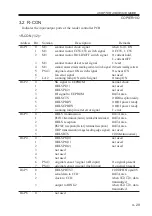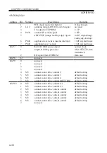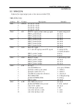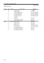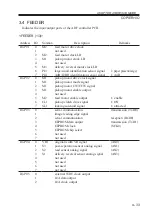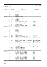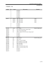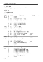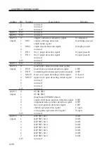
CHAPTER 4 SERVICE MODE
4-37
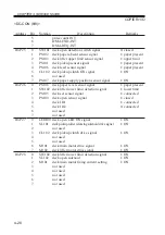
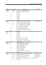
Address
IO-P05
(output)
IO-P06
(input)
IO-P07
(input)
IO-P08
(output)
IO-P09
(input)
Bit
0
1
2
3
4
5
6
7
8-15
0
1
2
3
4
5
6
7
8-15
0
1
2
3
4
5
6
7
8-15
0
1
2
3
4
5
6
7
8-15
0
1
2
3
4
5
Notation
M9
M9
PI4
M1
M1
PI17
PI3
PI14
PI1
PI22
Description
inlet feed motor phase A output
inlet feed motor phase B output
not used
not used
not used
not used
not used
not used
not used
stapler tray paper detection signal
punch motor clock detection signal
No. 1 feed motor phase A (output)
No. 1 feed motor phase B (output)
No. 2 feed motor clock input
inlet feed motor clock input
No. 1 feed motor clock input
delivery motor clock detection signal
not used
not used
not used
not used
not used
not used
tray lift motor clock signal 1
tray lift motor clock signal 2
swing motor clock detection signal
not used
stacker EEPROM CLK signal
stacker EEPROM data out signal
stitcher EEPROM CS signal
*LWR (input/output)
*HWR (output/output)
*RD (input/output)
*AS (input/output)
stacker unit EEPROM data (input)
not used
buffer path inlet paper detection signal
delivery paper detection signal
buffer path paper detection signal
inlet paper detection signal
stapler drive home position detection signal
not used
Remarks
0: paper present
0: paper present
1: paper present
0: paper present
0: paper present
1: HP
Summary of Contents for IR5000 - iR B/W Laser
Page 72: ...CHAPTER 2 STANDARDS AND ADJUSTMENTS 2 52 Blank Page ...
Page 104: ......
Page 224: ......
Page 234: ......

