CHAPTER 5 SELF DIAGNOSIS
5-9
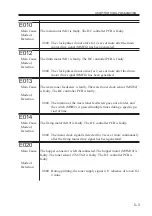
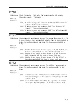
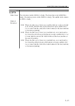
E710
Main Cause
The DC controller PCB is faulty. The reader controller PCB is faulty.
The main controller PCB is faulty.
Mode of
Detection
0001 When the main power is turned on, the IPC (IC5021) on the reader
controller PCB cannot be initialized.
0002 When the main power is turned on, the IPC (IC120) on the DC
controller PCB cannot be initialized.
0003 When the main power is turned on, the IPC (IC1003) on the main
controller PCB cannot be initialized.
E711
Main Cause
The connector is not connected properly. The remote diagnostic device PCB
is faulty. The copy data controller PCB is faulty. The ADF controller PCB is
faulty. The ADF controller PCB is faulty. The finisher controller PCB is
faulty.
Mode of
Detection
0001 Data has been written to the error register of the IPC (IC5021) on
the reader controller PCB four times or more within 1.5 secs.
0002 Data has been written to the error register of the IPC (IC120) on
the DC controller PCB four times or more within 2 secs.
0003 Data has been written to the error register of the IPC (IC1003) of
the main controller PCB four times or more within 2 secs.
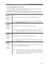
E712
Main Cause
The connector is not connected properly. The ADF 24-V power supply is
faulty. The ADF controller PCB is faulty. The reader controller PCB is
faulty.
Mode of
Detection
0001 Communication does not resume in 3 secs after data has been writ-
ten to the error register of the communication IC (IPC) of the ADF
controller PCB.
0002 The transmission bit is not enabled after a period of 10 sec at the
sync register of the IPC (IC5021) on the reader controller PCB.
Summary of Contents for IR5000 - iR B/W Laser
Page 72: ...CHAPTER 2 STANDARDS AND ADJUSTMENTS 2 52 Blank Page ...
Page 104: ......
Page 224: ......
Page 234: ......


