CHAPTER 4 SERVICE MODE
4-40
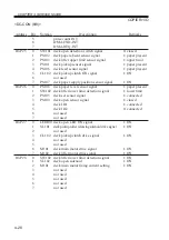
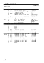
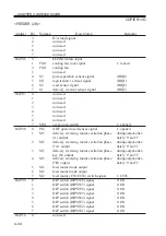
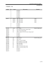
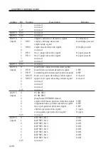
Address
IO-P21
(output)
IO-P22
AD-P01
AD-P02
AD-P03
AD-P04
AD-P05
AD-P06
AD-P07
DA-P01
Bit
0
1
2
3
4
5
6
7
8-15
0-15
-
-
-
-
-
-
-
-
Notation
SL7
SL3
SL2
SL1
SL5
SL6
Description
belt escape solenoid drive signal
buffer outlet solenoid drive signal
not used
buffer inlet solenoid drive signal
flapper solenoid drive signal
paddle solenoid drive signal
solenoid timer output
escape solenoid drive signal
not used
not used
dust full detection signal
24-V output OFF detection signal
horizontal registration detection signal 1
horizontal registration detection signal 2
horizontal registration detection signal 3
horizontal registration detection signal 4
trailing edge detection signal
punch LED ON signal (output)
Remarks
1: ON
1: ON
1: ON
1: ON
1: ON
1: ON
Summary of Contents for IR5000 - iR B/W Laser
Page 72: ...CHAPTER 2 STANDARDS AND ADJUSTMENTS 2 52 Blank Page ...
Page 104: ......
Page 224: ......
Page 234: ......

