CHAPTER 4 SERVICE MODE
4-34
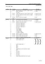
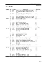
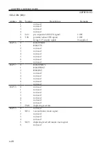
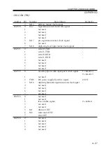
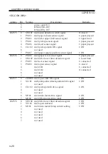
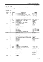
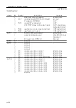
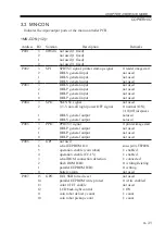
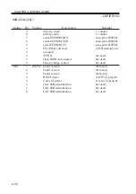
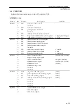
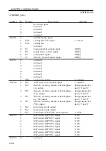
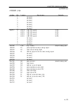
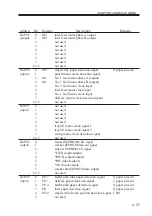
COPIER>I/O
<FEEDER (2/3)>
Address
IO-P06
IO-P07
IO-P08
IO-P09
IO-P10
Bit
3
4
5
6
7
0
1
2
3
4
5
6
7
0
1
2
3
4
5
6
7
0
1
2
3
4
5
6
7
0
1
2
3
4
5
6
7
0
Notation
FM1
FM1
S3
PI1
S2
S1
SW1
PI2
M3
M3
M3
M3
M2
M2
M2
Description
D/A load signal
not used
not used
not used
not used
EEPROM data input
cooling fan lock signal
cooling fan
not used
post-separation sensor signal
registration 1 sensor signal
read sensor signal
delivery reversal sensor signal
not used
not used
not used
not used
not used
not used
not used
cover open switch
ADF open/closed sensor signal
delivery reversing motor excitation phase
(A) output
delivery reversing motor excitation phase
(*A) output
delivery reversing motor excitation phase
key (B) output
delivery reversing motor excitation phase
(*B) output
feed motor mode output
feed motor mode output
feed motor (CW/CCW) switch signal
DIP switch (DIPSW8) signal
DIP switch (DIPSW7) signal
DIP switch (DIPSW6) signal
DIP switch (DIPSW5) signal
DIP switch (DIPSW4) signal
DIP switch (DIPSW3) signal
DIP switch (DIPSW2) signal
DIP switch (DIPSW1) signal
not used
Remarks
1: locked
(IRQ0)
(IRQ1)
(IRQ2)
(IRQ3)
1: opened
1: opened
during output, alter-
nately ‘0’ and ‘1’
during output, alter-
nately ‘0’ and ‘1’
during output, alter-
nately ‘0’ and ‘1’
during output, alter-
nately ‘0’ and ‘1’
1: CCW
0: ON
0: ON
0: ON
0: ON
0: ON
0: ON
0: ON
0: ON
Summary of Contents for IR5000 - iR B/W Laser
Page 72: ...CHAPTER 2 STANDARDS AND ADJUSTMENTS 2 52 Blank Page ...
Page 104: ......
Page 224: ......
Page 234: ......

