background image

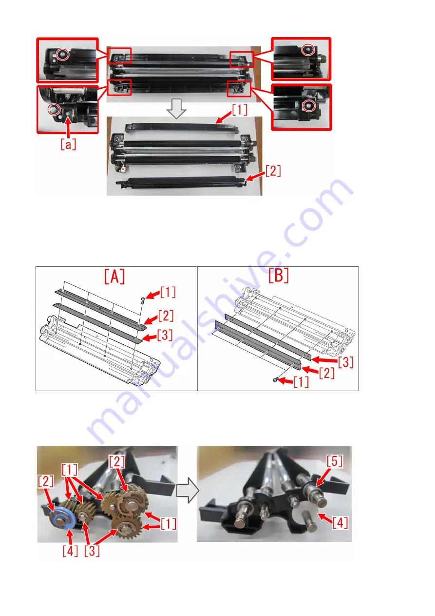
3) Refer to Service manual: "4 Parts Replacement and Cleaning" > "Image Formation System" > "Replacing the Secondary
Transfer Bias Roller Cleaning Blade" and remove the screws [1] x4pcs, blade [2] x1pc and blade adjuster plate [3] x1pc.
There are blades in 2 locations, right/left so remove them both. Shown below, [A] is the right blade and [B] is the left.
In addition, there may be multiple numbers of blade adjuster plates [3] attached. Remove them all in such case.

4) Remove 5pcs of gears [1], 2 pcs of N rings [2], 2pcs of E rings [3], 2pcs of spacers [4], 1pc of spacer [5]. Photo below shows
that new type of gears are installed. In the case of old type gears, one spacer [5] is not attached.

77

Summary of Contents for imagePRESS C10000VPSeries

Page 1: ...Troubleshooting Guide imagePRESS C10000VPSeries July 16 2019 Canon U S A Inc ...

Page 2: ... s Trouble Shooting Guide will be issued in the future when we have a new issue FAQ Measures against poor image density on the ends of the front and rear sides of the image Fixing failure due to shaved belt tension plate 012A Jam code due to lack of strength in the decurler drive roller 10mm wide soiled edge at the leading edge due to components in toner on papers being attached 0119 011A jam code...

Page 3: ...m due to the life of fixing belt 28 White horizontal lines at intervals of 2mm on green high density image caused by uneven charge amount of the ITB 29 Uneven density in a grid pattern on a high density image due to the uneven resistance on ITB 31 Soiling of spots at ITB intervals 33 Soiled image on the 1st side of 2 sided print 34 Soiled trailing edge soiled paper edge on both sides of 2 sided pr...

Page 4: ...sion roller holder breakage caused by applied load 108 Points to note when working on the surroundings of the halogen heater of fixing assembly 115 Points to note when installing a lower entrance guide 123 Jam Main Unit 124 0128 jam code due to high density image output in a high temperature humidity environment 124 Measure against 0300JAM wrong detection of double feed at feeding of Washi JPN Pap...

Page 5: ...taple Q1 W1 Booklet Q1 W1 Saddle AM2 AN2 Finisher AM1 AN1 224 E012 1080 due to the instable rotation of ITB drive iPC8000VP 228 Points to note in replacing the fixing external heat belt or external heating assembly 229 Notice of periodical replacement of the trimming blade and the heater Glue vat unit 230 Measure against failure after system version upgrade Multi Function Professional Puncher_A1 2...

Page 6: ...ature and high humidity environment the paper lint and wax component of toner combine and adhere to the Connection Lower Guide Roller 1 located at the outlet for the Primary Fixing Assembly When the paper lint and the wax component of toner which adhere to the roller are transferred to a paper the above symptom occurs Service work 1 Open the Sub Station Front Right Cover to pull out the Primary Fi...

Page 7: ...se an excessive temperature is added on OHT toner tends to melt beyond necessity The difference in glossiness made between the area where toner melts beyond necessity and the other image area causes the above mentioned symptom Service work 1 Have the customer log in from System Management Mode in user mode 2 Go to Select Settings Registration Paper Settings Paper Type Management Settings select an...

Page 8: ...Fine Black will not be displayed on the control panel change the setting value of Service Mode Mode List COPIER Option DSPLY SW IMGC ADJ to 1 The value is 0 by default 6 Press button for gloss Make sure the setting value a is set to 1 and press OK The setting range is from 4 to 4 0 by default Change of the setting value changes the fixing temperature 3 ...

Page 9: ...having shown the symptom and check that the symptom does not occur If the symptom improvement is inadequate decrease the setting value of step 6 down to 3 by 1 value while observing the symptom In case the decreased setting value 3 of step 6 does not improve the symptom please check another factor 4 ...

Page 10: ... amount varies among the toner on the paper When the electric charge amount varies the amount of toner that was once transferred to paper and to be attracted to the drum retransfer at the next station changes so that the toner amount on the paper becomes uneven and results in the above mentioned symptom A low humidity environment is likely to have this symptom as the primary transfer voltage is la...

Page 11: ...nd press Change Reference In case Adjust Primary Transfer Voltage will not be displayed on the control panel change the setting value of Service Mode Mode List COPIER Option DSPLY SW IMGC ADJ to 1 The value is 0 by default 6 If the Adjust Primary Transfer Voltage screen is displayed the presetting is completed 6 ...

Page 12: ...efault Change of the setting value changes the primary transfer voltage Caution Changing this setting may decrease the primary transfer voltage and bring poor image with black lowering of density mottling image etc 8 Output the image having shown the symptom and check that the symptom does not occur If the symptom does not improve then check other factors 7 ...

Page 13: ... in solidifying the wax components the difference in glossiness on the image surface tends to stand out and the above mentioned symptom occurs This symptom is likely to be seen on the high density image with high quantity of toner and heavy paper coated paper that is fixed at a high temperature Service work 1 Have the customer log in from System Management Mode in user mode 2 Go to Select Settings...

Page 14: ...Fine Black will not be displayed on the control panel change the setting value of Service Mode Mode List COPIER Option DSPLY SW IMGC ADJ to 1 The value is 0 by default 6 Press button for gloss Make sure the setting value a is set to 1 and press OK The setting range is from 4 to 4 0 by default Change of the setting value changes the fixing temperature 9 ...

Page 15: ...having shown the symptom and check that the symptom does not occur If the symptom improvement is inadequate decrease the setting value of step 6 down to 3 by 1 value while observing the symptom In case the decreased setting value 3 of step 6 does not improve the symptom please check another factor 10 ...

Page 16: ...age of the same portion is reduced The difference of the glossiness of the image generates the aforementioned symptom Service work 1 Select Settings Registration Adjustment Maintenance Maintenance Refresh Fixing Roller 1 and press Start button 2 Reference The time required for adjustment is approximate 40 seconds 2 Output the image having shown the symptom and check that the symptom does not occur...

Page 17: ...scattering inside the engine The pollution is cleaned in the area where the fixing separation claw comes in contact with so the glossiness is higher compared to the area where the claw does not come in contact with causing the 10mm wide highly glossy lines to occur Service work 1 Depending on the issue choose and perform one of a or b below a When 10mm wide semi glossy lines occur a 1 Select Servi...

Page 18: ...fresh roller worn out early b 2 Use heavy paper over 151gsm or coated paper over A3 LDR and perform the following Service mode Mode List COPIER Test Printabout10 sheets of duplex Yellow solid PG b 3 Output the image having shown the symptom and check that the symptom does not occur If the symptom does not improve then check other factors 13 ...

Page 19: ... symptom cannot be seen clearly on the heavy paper coated paper since the paper is fixed again in the secondary fixing assembly Service work 1 Open the sub station front right cover and take out the first fixing assembly 2 Fold the five ply lint free paper in four and clean the static eliminator 1 to become unraveled 3 Insert the first fixing assembly and close the sub station front right cover 4 ...

Page 20: ...icated in the step 7 and press Details Edit 9 Select Adjust Gross Fine Black and press Change Reference In case Adjust Gross Fine Black will not be displayed on the control panel change the setting value of Service Mode Mode List COPIER Option DSPLY SW IMGC ADJ to 1 The value is 0 by default 15 ...

Page 21: ... Changing the value may cause glossiness of image may slightly decrease 11 Output the image having shown the symptom and check that the symptom does not occur If the symptom improvement is inadequate decrease the setting value of step 10 down to 3 by 1 value while observing the symptom In case the decreased setting value 3 of step 10 does not improve the symptom please check anotherfactor 16 ...

Page 22: ...nges the image and this results in the above mentioned symptom Service work The ITB that is curled from being unused for a long time cannot be fixed in a short time If an ITB is left unused frequently take one of the two following measures a or b to prevent ITB from being curled a If ITB is left unused for a long time with the main power ON The ITB is rotated every certain period of time to preven...

Page 23: ... the direction of the arrow Holding the 2 grips c remove the Intermediate Transfer Unit Cover b 3 Turn the 2 Release Levers a of the Intermediate Transfer Unit in the direction of the arrow at the same time and pull the Intermediate Transfer Unit out until it stops by holding the grips b Caution Be sure to hold only the a part of the ITB Release Levers when turning the ITB Release Levers or your h...

Page 24: ...termediate Transfer Unit until it passes through the lock position approx 30 degrees and release both hands the Intermediate Transfer Unit will lower slowly Caution Do not insert your hands etc into the Intermediate Transfer Unit or Intermediate Transfer Unit Frame when lowering the Intermediate Transfer Unit b 7 While pushing the 2 Lock Release Springs a slide the Intermediate Transfer Unit towar...

Page 25: ... Caution Be careful not to get your fingers caught when sliding the Intermediate Transfer Unit toward the rear side b 8 Perform the work in the reverse order from the step b 3 20 ...

Page 26: ...t is already installed 1 Service mode level 2 COPIER Option IMG DEV ADJVPP M C K change the parameter from 1 to 4 Caution As the ring mark has never been observed with yellow color do not change the parameter of ADJVPP Y from 1 2 Execute the auto gradation adjustment b When the main unit is not installed yet Perform the following installation work to install the main unit 1 Execute the service mod...

Page 27: ... the test page paper used for adjustment 2 If the test page paper is not at a right angle 2 1 if the paper a edge is folded b correct the fold and perform reading again 2 2 if the paper a edge is lost due to trimming failure or damage b or if the test page image gets dirty c cancel the image position adjustment output test page using the new paper without trimming failure and execute the image pos...

Page 28: ...4 If the symptom does not improve then check other factors 23 ...

Page 29: ...ands or more of sheets of paper has passed through the device the paper dust or toner piled up on the belt pressure shaft increases and it may move to the pressure belt during the pressure belt displacement control Paper dust and toner moved to the pressure belt attaches onto the paper and this brings on the aforementioned symptom Service work 1 Remove the primary fixing pressure belt unit referri...

Page 30: ...he Secondary Fixing Roller Replacing the Secondary Fixing External Heat Belt Replacing the Secondary Fixing Refresh Roller and replace the Fixing Roller FL1 1152 000 the External Heat Belt FE3 1881 000 and the Refresh Roller Assembly FM3 2876 000 in the Secondary Fixing Assembly 2 Check the upper tandem guide a and if toner is attached follow the steps in Service Manual Disassembly Assembly Fixing...

Page 31: ...causes fine scratches on the fixing roller causing the lines on an image The following photos A show the state of that the cleaning brush roller 1 getting under the pressure refresh roller 2 The photos B show the proper state Service work When the pressure refresh roller is replaced assemble the parts in proper order referring Service Manual After the assembling make sure that the cleaning brush r...

Page 32: ...ed If the applicable paper type cannot be found make a duplicate copy 3 Select Adjust Image Position and preferences Change 4 Select Do Not Use Scanner in Adjust Image Position Select Method 5 Press Skew Correction Level Adjustment in Adjust Image Position and set the value to 2 for back side Press OK The configurable range is from 2 to 2 Default 0 6 Print the image which had the issue and ensure ...

Page 33: ...lines with a width of 7 mm wide a may occur The arrow indicates the feeding direction of media Cause Wrinkles appear on the well worn fixing belt 1 and it results in the symptom The green arrows indicate the paper delivery paths Service work Prepare new fixing belt FL0 0358 000 to replace with reference to Service Manual 28 ...

Page 34: ...retransfer which causes the above mentioned symptom Especially in the environment of the low humidity the symptom is more likely to occur due to the high primary transfer voltage Service work In order to lower the primary transfer voltage and avoid the above mentioned symptom implement the settings by following the steps below 1 Press Settings Registration and log in as an administrator and go to ...

Page 35: ...d 6 Press button of black of the primary transfer voltage to change the correction value a to 5 and press OK Reference The setting range is from 10 to 10 default 0 Changing the setting value will change the primary transfer voltage Attention Changing this setting value may cause the decreased primary transfer voltage and Bk image fault decreased density mottled blank on image etc 7 Output the imag...

Page 36: ...e As the number of pages printed on the ITB grows the electric resistance on the ITB becomes uneven causing the density of the transferred image to be uneven As a result the above symptom occurs Service work 1 Have the customer log in from System Management Mode in user mode 2 Go to Select Settings Registration Paper Settings Paper Type Management Settings select an appropriate paper type from amo...

Page 37: ...Mode Mode List COPIER Option DSPLY SW IMGC ADJ to 1 The value is 0 by default 6 In Adj Primary Transfer Voltage set the value to 10 for all colors The configurable range for the value is from 10 to 10 Default 0 Note Image failures decrease in density etc may occur because the primary transfer voltage decreases 7 Output the image having shown the symptom and check that the symptom does not occur If...

Page 38: ...tervals Spots appear at intervals of approx 5 A3 size sheets at continuous output If it can be confirmed that the positions of the spots in the horizontal scanning direction are always the same the spots can be judged to be attributed to the ITB When it is highly possible that the ITB is the cause check its surface Service work Dry wipe the foreign matter attached to the ITB surface Caution Do not...

Page 39: ... the Pressure Roller When 2 sided printing is performed in this state the soiling of the Pressure Roller is adhered to the image on the 1st side on which toner is deposited at the time the 2nd side passes through the Secondary Fixing Assembly Service work Execute the following service mode to perform forced Pressure Roller cleaning Service Mode COPIER FUNCTION CLEANING FX2PR CL After the execution...

Page 40: ...s output of low duty image or in the high temperature environment causing the Post secondary Transfer Guide to be excessively soiled by toner When 2 sided printing is performed in this state this Bk toner is attached for 20 mm around the center of the paper leading trailing edge or of the paper edge on the 1st and 2nd sides of 2 sided print Service work Clean the Post secondary Transfer Guide 35 ...

Page 41: ...uck between the cylinder and the blade in the developing unit Service work Remove foreign matter by the following procedure 1 Remove the Developing Cylinder Upper Cover 1 2 Screws 2 2 After inserting the Toner Congestion Removal Sheet 1 packed with the host machine between the Developing Cylinder and the blade remove foreign matter by moving the sheet like you draw circles 36 ...

Page 42: ...3 Output about 10 test prints to verify the effect 37 ...

Page 43: ...e Secondary Transfer Outer Belt and the ITB Toner may newly be attached onto the fixed toner which has been accumulated as the life advances causing toner to attach to the back side of the paper when it passes through the secondary transfer area Service work Remove the secondary transfer outer belt unit from the main body and wipe the surface of the belt that engages with the tension roller metal ...

Page 44: ...ngs Paper Type Management Settings select an appropriate paper type from among the list press Duplicate button and then OK button 3 Enter any name as the duplicated paper type and press OK button 4 Select the paper type duplicated in the step 3 and press Details Edit 5 Select Adj Secondary Transfer Volt and press Change Note In case Adj Secondary Transfer Volt will not be displayed on the control ...

Page 45: ... Attention The density on a high density image may be lower when the secondary transfer voltage gets lower by changing this setting If the symptom does not improve then check other factors 40 ...

Page 46: ...agement Mode in user mode 2 Go to Select Settings Registration Paper Settings Paper Type Management Settings select an appropriate paper type from among the list press Duplicate button and then OK button 3 Enter any name as the duplicated paper type and press OK button 4 Select the paper type duplicated in the step 3 and press Details Edit 5 Select Adj Sec Transfer Belt Speed and press Change Note...

Page 47: ...ing range is from 3 to 3 0 by default Changing this setting will accelerate the speed of the secondary transfer belt CAUTION Vertical scanning magnification ratio slightly becomes larger If adjustment is required refer to Service Manual Adjustment Vertical Scanning Magnification Ratio Adjustment 9 Output the image having shown the symptom and check that the symptom does not occur If the symptom do...

Page 48: ...e paper with high density image the accumulated toner on the both ends of fixing inlet guide will adhere to the edges of the media Therefore the above mentioned symptom occurs Service work 1 Clean the fixing inlet guide referring Service Manual Disassembly Assembly Fixing System Cleaning the Primary Fixing Inlet Guide and Cleaning the Secondary Fixing Inlet Guide Note The cleaning timing for the p...

Page 49: ...04 Developing Assembly d 50mm Primary Transfer Roller FC8 6852 e 66mm Secondary Transfer Inner Roller FM1 A359 2ND TRNSFR INNER ROLLER ASS Y f 75mm Secondary Transfer Outer Roller FE4 6066 g 198mm Secondary Transfer Outer Belt FE3 1953 h 69mm Secondary Transfer Outer Belt Drive Roller FM1 M250 BELT DRIVE ROLLER ASSEM BLY i 252mm Fixing Roller FL1 1151 Primary Fixing FL1 1152 Secondary Fixing j 220...

Page 50: ...E ROLLER ASSEMBLY FM1 M250 i When the interval is 252mm pitch check Fixing Roller i FL1 1151 of the Primary Fixing Assembly or Secondary Fixing Assembly j When the interval is 220 mm pitch check Pressure Belt j FL0 0358 of the Primary Fixing Assembly k When the interval is 190 mm pitch check Pressure Roller k FL0 0515 of the Secondary Fixing Assembly l When the interval is 189mm check External Hea...

Page 51: ...er belt drive failure resulting in the above mentioned symptom Reference There is a possibility that the symptom occurs in all the 4 shafts shown in the Figure A however the scrape occurs most on the shaft 1 for structural reasons If the shaft is replaced by itself prepare the new type shafts to replace The scraped shaft cannot be limited to 1 location but other shafts may be scraped Therefore rep...

Page 52: ...replacing the 4 shafts at the same time is recommended Part Number Description Number FE4 6162 010 SHAFT 2 2 FE4 6163 010 SHAFT 1 1 FE4 6164 010 SHAFT 5 3 FE4 6165 010 SHAFT 6 4 If the shaft is replaced by itself it will take about one hour longer than the unit replacing work of the drive assembly When the symptom occurs chips of the drive shaft may be found in the lower part of the 2nd transfer c...

Page 53: ... remove the pre fixing feed upper cover 2 5 Disconnect the connectors 1 in the 3 sections and remove the cable from the saddle 6 Remove the sensor flag 1 and the tension spring 2 7 Remove the 4 screws 1 8 Remove the 3 screws 1 48 ...

Page 54: ...hips of the shaft are scattered in the lower part of the 2nd transfer cleaner assembly wipe out the chips with a cloth 11 Apply the same amount of super lube grease as 3 grains of rice 60mg respectively to the entire surface of the gear on the rear side and roller of the new transfer cleaner drive unit FM1 H026 000 Reference Clean the gear and apply the grease to it after every 1000K sheet If the ...

Page 55: ...at the hole of the 2nd transfer drive motor sheet metal and the shaft match If the shaft has a stepped section check that it fits to the hole properly 15 Assemble in the order of the steps 7 6 and 5 16 Turn the gear 1 clockwise seeing from the front to check that it including the transfer cleaner drive unit turns smoothly And insert the connecting part 2 of the connector into the hole a 17 Assembl...

Page 56: ...LEANER DRIVE UNIT 1 0 333 New FM1 H026 010 TRANSFER CLEANER DRIVE UNIT 0 1 2 Old FY9 6005 000 LUBE SUPER LUBE GREASE 85G 0 1 New 3 Old FE4 6162 000 SHAFT 2 1 0 333 New FE4 6162 010 SHAFT 2 0 1 4 Old FE4 6163 000 SHAFT 1 1 0 333 New FE4 6163 010 SHAFT 1 0 1 5 Old FE4 6164 000 SHAFT 5 1 0 333 New FE4 6164 010 SHAFT 5 0 1 6 Old FE4 6165 000 SHAFT 6 1 0 333 New FE4 6165 010 SHAFT 6 0 1 Countermeasure ...

Page 57: ...k side non printed side of the paper Cause When printing on one sided heavy paper with face down delivery the leading edge and trailing edge of the paper rub strongly against the flapper a in passing through the delivery reverse unit which may result in the above mentioned symptom One sided and two sided printing with face up delivery does not cause the symptom Service work Set the delivery operat...

Page 58: ...distribution of moisture on paper Service work 1 Have the customer log in from System Management Mode in user mode 2 Go to Select Settings Registration Paper Settings Paper Type Management Settings select an appropriate paper type from among the list press Duplicate button and then OK button 3 Enter any name as the duplicated paper type and press OK button 4 Select the paper type duplicated in the...

Page 59: ... will not be displayed on the control panel change the setting value of Service Mode Mode List COPIER Option DSPLY SW IMGC ADJ to 1 The value is 0 by default 8 Press button for gloss Make sure the setting value a is set to 1 and press OK The setting range is from 4 to 4 0 by default Change of the setting value changes the fixing temperature Caution Changing the value may cause glossiness of image ...

Page 60: ...ler is somewhat rough the refresh roller might give fine scratches to the fixing roller in its operation and this result in the above mentioned symptom Service work When the aforementioned symptom has occurred prepare and replace with the new type refresh roller FM1 T299 000 referring to the service manual Photo A shows the old type refresh roller shaft photo B and C show the new type Change the e...

Page 61: ...owing the procedure below 1 When the aforementioned symptom has occurred identify which drum unit among Y M C Bk causes the uneven density at regular intervals and prepare the brand new 192T gears FL3 0561 010 as needed Note For uneven density with Y replacing the 192T gear FL3 0561 010 connected to the Y drum drive assembly is recommended For uneven density with M replacing the 192T gears FL3 056...

Page 62: ...ear covers 3 Remove the 2 screws 1 and the flywheel 2 4 Loosen the 2 screws 2 fixed to the shaft remove the screw 3 and then the flywheel mount 1 5 Replace the 192T gear 1 with a brand new one 6 Repeat the works from the step 3 to 5 to the 192T gears to be replaced 7 Reassemble the parts in reverse order from the step 4 Service parts No Part Number Description Q ty Fig No 1 Old FL3 0561 010 GEAR 1...

Page 63: ...ast pages of glued stacked of sheets due to the edges of round holes a of mini gripper 1 being located at the upper and lower sides of main gripper assembly when transferring Service work If the above mentioned symptom occurs prepare the sheet kit 4Y8 3138 000 to affix the sheet on the mini gripper being located on the upper and lower sides of main gripper assembly 1 Turn off the main power of per...

Page 64: ...ION To keep the machine running in service mode be sure to do so with the trimming assembly stowed inside 6 Plug the power cord in the wall outlet 7 Turn on the power switch and then perform machine initialization operation 8 Turn off the power switch 9 Turn on SW1 1 on the service PCB and set the machine in service mode 59 ...

Page 65: ...e PCB and then press the push switch PSW1 3 three times to stop the mini gripper at the vertical position 12 Turn off the main switch and unplug the power cord from the wall outlet 13 Remove the filter case unit 3 screws 14 Remove the glue transport stay 1 screw 60 ...

Page 66: ...pers 1 2 screw Attention Be careful not to drop the screws into the machine during the operation 16 Stand in front of the machine to face the front side and then remove screws 2 fixing the mini gripper 1 2 screw Attention Be careful not to drop the screws into the machine during the operation 17 Remove the screw 2 being the left side of mini gripper 1 on your left and then disconnect the fixed gro...

Page 67: ...at 1 one mini gripper 2 has been taken from the back side of machine 20 Prepare the sheet kit 4Y8 3138 000 to affix the sheet on the mini gripper removed from the main gripper along the following reference lines Affixing reference line a Affix the left edge of sheet 1 at where it is within 1mm from the edge of mini gripper Affixing reference line b Affix the upper edge of sheet 1 at where it is wi...

Page 68: ...tion of unit 1 being the side of mini gripper is correct and then put the mini gripper Photo A shows upside down position of the unit on the side of mini gripper Photo B shows the correct position Service parts No Part Number Description Q ty Fig No 1 Old P51 New 4Y8 3138 000 SHEET KIT 0 1 63 ...

Page 69: ...drums perform procedure 2 and later for every unit to complete the work 2 Refer to the service manual to remove a drum unit from the main body 3 Moisten a lint free paper with alcohol wipe off the toners fused on the drum thoroughly by wiping from left to right in the scanning direction as shown in the photo arrows Note Change the lint free paper every time after use Be sure to use lint free paper...

Page 70: ...unit on a drum unit and install it in a main body 8 If multiple drum units are to be replaced conduct procedure 2 to 7 every time before proceeding to next step Perform auto gradation adjustment Full PASCAL Settings Registration Adjustment Maintenance Adjust Image Quality Auto Adjust Gradation then select Full Adjustment Check the output images made out of Auto Adjust Gradation and confirm that th...

Page 71: ...d replace the following parts Replace the torsion spring both on the front and rear sides at the same time even if only either of them is damaged New type torsion spring front side FU2 0419 010 New type torsion spring rear side FU2 0420 010 Washer XD1 1104 122 2 pieces Hanarl UD 321 FY9 6037 000 New E ring 2 pieces Reference Photo A shows the old type torsion spring and Photo B shows the new type ...

Page 72: ...2 Lift the lever C A4 1 and open the primary fixing inner delivery unit 2 3 Loosen the 2 screws 1 and slide the fixation pins 2 in 2 locations in the arrow directions 4 Open the upper unit 1 slowly 67 ...

Page 73: ...ping as shown in the photo below 6 Remove the E ring 1 and remove the damaged torsion spring front side 2 7 Apply the hanarl evenly to the entire circumference of the collection roller pressure shaft a 8 Attach the new type torsion spring front side FU2 0419 010 1 68 ...

Page 74: ... side of the washer 1 10 Place the washer 1 so that the hanarl applied surface a faces the torsion spring front side 2 11 Apply the hanarl evenly to the entire surface b of the washer where the hanarl was not applied in the step 10 69 ...

Page 75: ...U2 0419 000 TORSION SPRING 2 0 815 855 New FU2 0419 010 TORSION SPRING 0 2 2 Old FU2 0420 000 TORSION SPRING 2 0 815 855 New FU2 0420 010 TORSION SPRING 0 2 3 Old 815 855 New XD1 1104 122 WASHER 0 4 4 Old FY9 6037 000 HANARL UD 321 1 1 815 855 New Factory Measures Change the torsion spring into the new type torsion spring front side rear side and add the washer and application of the hanarl Counte...

Page 76: ...roblem The parts set as a 2ND TRNSFR CLEANER GEAR SET FM1 U402 000 are listed below Comparative table of parts to be replaced Fig No Key No Parts to be replaced Main body side 2ND TRNSFR CLEANER GEAR SET FM1 U402 000 PART NUMBER DESCRIPTION PART NUMBER DESCRIPTION 335 1 FE4 6174 POSITIONING ROLLER FE2 A988 POSITIONING ROLLER 2 FE4 6174 POSITIONING ROLLER FE4 6174 POSITIONING ROLLER 3 FU2 1491 15T ...

Page 77: ... SET 4 Apply the super lube grease in an amount of a grain of rice approximately 20mg on the tooth of the following gears evenly 3 FU2 2543 15T GEAR 4 FU2 2544 21T 15T GEAR 5 FU2 2545 18T GEAR 8 FU2 2547 18T GEAR 5 Remove 9 to 11 from the transfer cleaner drive unit b and replace with the parts of 2ND TRNSFR CLEANER GEAR SET 6 After installing the transfer cleaner drive unit on the belt cleaner as...

Page 78: ...0 POSITIONING ROLLER 2 1 333 New FE2 A988 000 POSITIONING ROLLER 0 1 8 Old 333 New FE2 B033 000 SPACER 0 1 9 Old FU2 1501 000 20T GEAR 1 0 333 New FU2 2548 000 20T GEAR 0 1 10 Old FU2 1503 000 16T GEAR 1 0 335 New FU2 2549 000 16T GEAR 0 1 Factory measures In order to increase strength the materials of gears and positioning rollers are changed A is the old type and B is the new type parts In addit...

Page 79: ...eaning capability decreases As a result the collection roller is soiled gradually and it results in the above symptom Remedy Answer When the above symptom occurs prepare the new tension spring FU2 1836 000 and replace it by following the steps below For every web roller there are 2 tension springs located one each in the front A and the back B Even when only one of them breaks be sure to replace b...

Page 80: ...ep 2 to both sides one for each side Note When attaching the bushing position the cutout section b of the bushing to align with the section a of the front web side plate A and the rear web side plate B 6 Attach the fixing web unit to the machine Service parts No Part Number Description Q ty Fig No 1 Old FU2 1836 000 SPRING TENSION 2 2 830 New 75 ...

Page 81: ... may cause cleaning failure resulting in the above mentioned symptom Remedy Answer When the above mentioned failure occurs prepare a newly assigned service part the cleaner front side plate FL0 5502 000 and replace it by following the steps below 1 Refer to Service manual 4 Parts Replacement and Cleaning Image Formation System Replacing the Secondary Transfer Cleaning Unit Edge Seal Bases Rear and...

Page 82: ...re blades in 2 locations right left so remove them both Shown below A is the right blade and B is the left In addition there may be multiple numbers of blade adjuster plates 3 attached Remove them all in such case 4 Remove 5pcs of gears 1 2 pcs of N rings 2 2pcs of E rings 3 2pcs of spacers 4 1pc of spacer 5 Photo below shows that new type of gears are installed In the case of old type gears one s...

Page 83: ...t B Cleaning brush roller Left 1 Cleaning brush rolle 1 Cleaning brush roller 2 E ring 2 E ring 3 Gear 3 Washer 4 Bearing 4 Gear 5 Bearing 6 Remove the E rings and bearings of the bias roller 1 and bias roller 2 2 respectively 7 Bias roller 1 shall be removed by sliding it to a direction and detach from side b Remove the bias roller 2 in the same manner 8 Remove 2pcs of screws 1 while holding the ...

Page 84: ... 1 and lower blade support 2 in the arrow direction If it expand cleaner rear side plate 3 may break 10 Install the newly assigned service part cleaner front side plate FL0 5502 000 1 by inserting in the direction shown in arrow slowly Reference When installing the cleaner front side plate be sure to fit in the shaft 2 and the 3 bosses a as shown below 79 ...

Page 85: ...nstalled status without gap 11 Assemble the parts by reversing the procedures from the step 8 Note Note the followings when installing the parts Be careful with its orientation when installing a bias roller bias roller 2 in step 7 The shaft end of a bias roller at the cleaner front side plate side has D cut a The shaft end of a bias roller 2 at the cleaner front side plate side has E ring groove b...

Page 86: ...ions turn ON the main power SW 13 Execute Exe Sec Trns Cln Brsh Roll ini inst mode in service mode Service Mode COPIER FUNCTION INSTALL INS 2TCL 14 Conduct blank printing in duplex mode for about 10pcs 15 Check and confirm that the output media is clean 15 a If the media is clean all works are done 15 b If any stain is seen prepare the following parts and proceed to step 16 as needed FC7 9749 000 ...

Page 87: ... 2pcs of 0 1mm spacers remove one to make it 0 1mm thick Example 2 In case there is 1pc of 0 3mm spacer remove this and attach 2pcs of 0 1mm spacers instead 18 Assemble the parts by reversing the procedures from step 3 and then conduct steps 12 to 15 once more Service parts No Part Number Description Q ty Fig No 1 Old New FL0 5502 000 SIDE PLATE CLEANER FRONT 0 1 335 Countermeasure cut in serial n...

Page 88: ...arrows show the paper feeding direction Cause The filter base 1 inside the exhaust duct unit ozone filter A of the sub station is clogged and poor exhaust inside the machine occurs This causes stains to adhere to the etching grid plate on the end of the front side and on the end of the rear side of the primary corona assembly and charging failure occurs resulting in poor image density The photos b...

Page 89: ... referring to its respective estimated cleaning timing and estimated life sheets per replacement If the filters with are clogged the above mentioned symptom is likely to occur Especially if the filter base is clogged the above mentioned symptom is more likely to occur The estimated cleaning timing for the filter base is every 2 000 000 sheets This is the same timing as the estimated life sheets pe...

Page 90: ... 3 Old FL2 0464 000 HOLDER WIRE CLEANING PAD 1 1 550 New 4 Old FL2 4271 000 BLOCK WIRE CLEANING PAD 1 1 550 New 5 Old FC6 8137 000 BASE FILTER 1 0 111 New FC6 8137 010 BASE FILTER 0 1 Countermeasure cut in serial numbers in factory Model Serial No IPR C10000VPSR FS US J WBE15541 IPR C10000VPSR FS EUO WBF15474 IPR C10000VPSR FS CN WBG15042 85 ...

Page 91: ...ndition whereas B is a deformed condition due to detachment and abrasion of a transmission shaft Keep on using the machine with the above state may lead to fixing failure Cause The transmission shaft is controlled not to detach from the belt tension plate 1 by an E ring A However as shown in B the transmission shaft may be detached from the uncontrolled part a In such case due to abrasion between ...

Page 92: ...mation is observed Rear belt tension plate FC6 0364 Replace it if abrasion or deformation is observed E ring Do note reuse the E ring when removed Prepare a new one 1 Refer to Service manual 4 Parts Replacement and Cleaning Fixing System Disassembling the Primary Fixing Pressure Belt Unit and remove the 1st Fixing Pressure belt Note Be careful not to touch the surface of the fixing pressure belt a...

Page 93: ...asher 2 attached There is no difference between the two sides of the new type toothed lock washer Photo at the right end below is a view from the rear side so that the status of the E ring 1 could be seen 5 Assemble the parts by following the procedure 3 in reverse order Reference When installing a tensioner stopper 1 and a stopper retaining plate 2 set the parts as shown in the photo below lay a ...

Page 94: ...ual Service parts No Part Number Description Q ty Fig No 1 Old FS5 6488 000 WASHER 2 0 813A 813B New FE2 A267 000 WASHER TOOTHED LOCK 0 2 2 Old FC6 0335 000 SHAFT TRANSMISSION 1 1 813A 813B New 3 Old FM1 A385 010 FIXING PRESSURE BELT ASSEMBLY 200V 208V 1 0 813A New FM1 A385 020 FIXING PRESSURE BELT ASSEMBLY 200V 208V 0 1 4 Old FM1 A409 020 FIXING PRESSURE BELT ASSEMBLY 400V 1 0 813B New FM1 A409 0...

Page 95: ... countermeasure cut in serial numbers As the production of imagePRESS C7000 series has ended there is no countermeasure cut in serial numbers As the production of imagePRESS C7011 C7010 C6011 C6010 series has ended there is no countermeasure cut in serial numbers 90 ...

Page 96: ... button and then OK button 3 Enter any name as the duplicated paper type and press OK button 4 Select the paper type duplicated in the step 3 and press Details Edit 5 Select Adj Paper Convey 2 Sided and press Change 6 Change the value of Adj Paper Convey 2 Sided to 1 and press OK button The range of setting is from 3 to 3 0 by default 7 Print the image which had the issue and ensure that the sympt...

Page 97: ... on plate in some cases due to insufficient feeding force caused by the height of paddle and feed power As a result staple misalignment may occur Mechanism of only the last sheet of paper being misaligned and stapled In addition to the cause mentioned above below is information on why only the last sheet is misaligned When the sheets in middle up to the second sheet to last sheet of each staple jo...

Page 98: ...on the intermediate process tray does not warp when pushing the paper Note Perform adjustment by placing only 1 sheet of A4 paper If pushing the paper too much with the front alignment plate alignment will get worse When the initial setting value is 0 By pressing SW383 once the LED 3 indicates 1 and the front alignment plate 4 shifts to the front by approx 0 2mm In the same way by pressing SW384 o...

Page 99: ...ont once with a finger and let go A 10 After the alignment plate adjustment is complete return all the bit switches in SW382 to OFF A 11 To check the state print multiple stapled sets A 12 Check staple quality of the printed document The specification of staple misalignment for finisher is within 2mm depending on installation environment of the machine and papers used After having the alignment pl...

Page 100: ...omes lower when setting to 1 B 4 Press switch SW385 again to complete this adjustment Next proceed to C Adjusting Position of Feed Belt C Adjusting Position of Feed Belt C 1 Set DIP SW382 on the switch PCB as shown in the figure below Note SW1 SW6 and SW7 are ON C 2 Press switch SW385 to start position adjustment of the feed belt 95 ...

Page 101: ...mm refer to the step B Adjusting Paddle Height and the step C Adjusting Position of Feed Belt and change the paddle height adjustment value to 2 and the feed belt position adjustment value to 4 Caution In the step B Adjusting Paddle Height and the step C Adjusting Position of Feed Belt be sure to first change the paddle height adjustment value to 1 and the feed belt position adjustment value to 2 ...

Page 102: ...t of the machine and papers used After having the alignment plate and the paddle height adjusted to 2 and the feed belt position to 4 staple misalignment should improve to be within 2mm If staple misalignment on all 100 sets of the printed document is within 2mm the work completes here If staple misalignment is more than 2mm check for other factors 97 ...

Page 103: ...tach to the back up roller 3 and the transmission shaft 4 The attached components gradually damage the transmission shafts 4 in the upper delivery guide assembly 1 and the lower delivery guide assembly 2 and pollution accumulates in the damaged area a resulting in the above symptom Remedy Answer When the above symptom occurs prepare the new type transmission shaft and super lube grease and replace...

Page 104: ...ver 2 remove the delivery reverse cover 2 3 Remove the 3 screws 4 and then remove the delivery reverse cover 1 5 and the delivery upper guide cover 6 3 Remove the tension spring 2 located at the top of the back up roller 1 4 Remove the screw 1 and the connector support plate 2 located in the rear side of the delivery reverse unit Then remove the connector 3 in the back of the connector support pla...

Page 105: ...lide rail located in the rear side of the delivery reverse unit a 2 Remove the screw 1 located in the rear side of the delivery reverse unit and pull out the positioning pin Rear 2 in the direction of the arrow a 3 Move to the front side of the machine Remove the screw 1 in the front side of the delivery reverse unit and pull out the positioning pin Front 2 100 ...

Page 106: ...below and remove the upper delivery guide assembly 1 a 5 Clean the pollution on the driven roller surface a with lint free paper moistened with alcohol a 6 Remove the E ring 1 and the bearing 2 from the transmission shaft 101 ...

Page 107: ...ying super lube grease to the transmission shaft be sure not to apply it to any areas of the shaft other than where the bearings are engaged a 10 Attach the parts in the reverse order from the step a 7 to the step a 1 If continuing on to replace the transmission shaft in the lower delivery guide assembly proceed to the step b below If replacing the transmission shaft in the upper delivery guide as...

Page 108: ...ews 3 and then remove the motor unit 4 Note Be careful when removing the motor unit 4 as the gear and the shaft 5 may come off easily b 2 Remove the gear the dowel pin 1 the 2 E rings 2 and the bearing 3 from the transmission shaft located in the front side of the delivery reverse unit b 3 Remove the light blue harness 1 located in the rear side of the delivery reverse unit from the 3 harness guid...

Page 109: ...ddles remove the 2 screws 2 and move the harness guide sheet metal 3 in the direction of the arrow b 5 Remove the screw 1 Then remove the gear shaft unit 2 and the support plate 3 b 6 Pull and remove the transmission shaft 1 with the gear 2 attached 104 ...

Page 110: ...rts removed in the step b 7 Note When applying super lube grease to the transmission shaft be sure not to apply it to any areas of the shaft other than where the bearings are engaged b 9 Attach the parts in the reverse order from the step b 6 to step b 1 Note When attaching the parts apply about the size of a rice grain 20mg of super lube grease to the area where the transmission shaft and bearing...

Page 111: ...FT TRANSMISSION 1 0 352 New FE8 3617 010 SHAFT TRANSMISSION 0 1 3 Old FM1 H041 010 DELIVERY GUIDE ASSEMBLY UP PER 1 0 351 New FM1 H041 020 DELIVERY GUIDE ASSEMBLY UP PER 0 1 4 Old FM1 H080 010 DELIVERY GUIDE ASSEMBLY LOWER 1 0 352 New FM1 H080 020 DELIVERY GUIDE ASSEMBLY LOWER 0 1 Countermeasure cut in serial numbers in factory Model Serial No IPR C10000VPSR FS US WBE15582 IPR C10000VPSR FS EUO WB...

Page 112: ...t and a finger is scanty to push the shaft support with the finger the shaft support may be tilted and result in the above mentioned symptom Service work To push the releasing claw a of the secondary transfer outer roller holder front shaft support be sure to put a finger against the whole face of the releasing claw a The figure A shows a state where the finger is put against the whole face of the...

Page 113: ...ondary transfer outer belt tension roller holder may break B Cause a Secondary transfer outer belt breakage a 1 The factor due to the vibration of the back up roller At the first time of the production start the machine was transported with the secondary transfer outer belt 2 set Therefore the back up roller 1 of the secondary transfer outer belt assembly repeatedly vibrated upward and downward an...

Page 114: ...cates the state that the side seal front is attached with unfixed edge a photo B indicates the state that the side seal is correctly attached b a 3 The factor due to the wrong attachment position of belt edge seal for the belt cleaner lower cover The belt edge seal in the belt cleaner lower cover presses the secondary transfer outer belt assembly against the belt drive roller 1 and rollers 2 toget...

Page 115: ... the edge of the claw Service work Based on the issue mentioned below follow the steps and replace the parts a Secondary transfer outer belt breakage 2ND TRANSFER BELT ASSEMBLY Prepare the new type 2nd transfer belt assembly FM1 A345 020 Refer to Service Manual and replace the assembly b Secondary transfer outer belt breakage BELT CLEANER ASSEMBLY Prepare new type side seal front rear and the belt...

Page 116: ...es can be used together but it is recommended to replace the both parts to the new type The figure A is the old type outer roller holder and the figure B is the new type outer roller holder Reference The shape of the tension roller edges 1 2 is changed and the claw of the outer roller holder a is removed The edge 1 is extended in length for 2 5mm The edge 2 is extended in length for 7mm and the sh...

Page 117: ...ring and the stopper plate removed in the step c 4 to the new type roller holder FE4 6074 010 c 6 Insert the sheet metal 1 to the front shaft part of the new type tension roller FE4 6069 010 and fix the roller holder 2 assembled in the step c 5 by the new type E ring XD2 1100 502 Reference There is a groove on the front shaft part of the tension roller Be sure to attach the roller holder to the sh...

Page 118: ...ficult to release tension as the claw of the roller holder is short 2mm in this case Recommended to replace the tension roller to the new type D The combination of the new type parts Service parts No Part Number Description Q ty Fig No 1 Old FM1 A345 010 2ND TRANSFER BELT ASSEMBLY 1 0 334 New FM1 A345 020 2ND TRANSFER BELT ASSEMBLY 0 1 2 Old FE4 6074 000 HOLDER ROLLER 1 0 334 New FE4 6074 010 HOLD...

Page 119: ...1 A345 020 for the replacement Countermeasure cut in serial numbers in factory Model Serial number a b imagePRESS C10000VP Series ME US WBC10408 WBC10459 imagePRESS C10000VP Series ME CN WBD00521 WBD00522 imagePRESS C10000VP Series ME EUO WEJ10447 WEJ10554 a Measure against the secondary transfer outer belt breakage b Measure against the claw of secondary transfer outer belt tension roller holder ...

Page 120: ...en heater is secured in the correct position when visiting the user replacing the halogen heater or when attaching detaching the unit having the halogen heater Reference The voltage of the fixing assembly can be identified by the colors of the one cable side of the fixing external heat belt halogen heater Model Voltage Color of cable imagePRESS C10000VP series 200 208 White 400 Black imagePRESS C7...

Page 121: ...ssembly are different Perform the steps A and B for the primary fixing assembly and perform the steps A B and C for the secondary fixing assembly A Checking the halogen heater of the external heat belt A 1 Check that the heater mounting plate on the rear side and the insulator of the halogen heater end are correctly attached A 2 Check that the heater mounting spring on the front side and the insul...

Page 122: ...D 1 Check if the halogen heater cable is appropriately wired The photo A shows a state where the halogen heater cable 1 on the rear side is adequately arranged along the guide The photo B shows a state where the halogen heater cable 1 on the rear side is pinched a between the guide and the separation drive mount In this case fix the wiring correctly The photo C shows a state where the halogen heat...

Page 123: ... heater of the external heat belt A 1 Check that the heater mounting plate on the rear side and the insulator of the halogen heater end are correctly attached A 2 Check that the heater mounting spring on the front side and the insulator of the halogen heater end are correctly attached B Checking the halogen heater of the fixing roller B 1 Check that the heater mounting plate on the front side and ...

Page 124: ...Check that the heater mounting plate on the front side and the insulator of the halogen heater end are correctly attached C 2 Check that the heater mounting spring on the rear side and the insulator of the halogen heater end are correctly attached D Checking the halogen heater cable of the fixing pressure belt assembly D 1 Check if the halogen heater cable is appropriately wired 119 ...

Page 125: ...ide The white dashed line indicates the correct route that the halogen heater cable inside of a guide plate is wired imagePRESS 1135 Series A Checking the halogen heater of the external heat belt Check the following just before attaching the fixing external heat assembly to the fixing assembly A 1 Check that the heater mounting plate on the rear side and the insulator of the halogen heater end are...

Page 126: ... side and the insulator of the halogen heater end are correctly attached C Checking the halogen heater of the pressure roller C 1 Check that the heater mounting plate on the front side and the insulator of the halogen heater end are correctly attached C 2 Check that the heater mounting spring on the rear side and the insulator of the halogen heater end are correctly attached 121 ...

Page 127: ...end is detached secure the insulator in the correct position If the insulator of the halogen heater end of the working machine is detached check whether the halogen heater cables are damaged If they are damaged to the state where the conductor is visible as shown in the photo below replace the halogen heater by referring to Service Manual 122 ...

Page 128: ...late which was broken from the base Cause When installing a lower entrance guide 1 from the direction shown in arrow below the bent part a of the lower entrance guide could hit the varistor plate 2 causing the above symptom Remedy Answer 1 When installing a lower entrance guide 1 to the secondary transfer outer roller holder front 2 be careful with the direction to be installed a or b is the corre...

Page 129: ...lded corner as a result If a sheet of paper that is curled upward has a folded corner at the flapper a that switches the single fixing path and the tandem fixing path the above mentioned symptom may occur Service work Reference Improving a state of preservation of paper may be effective in resolving a trouble in some cases Explain to a customer that unused or remaining paper should be stored by be...

Page 130: ...k and press Change Reference In case Adjust Gross Fine Black will not be displayed on the control panel change the setting value of Service Mode Mode List COPIER Option DSPLY SW IMGC ADJ to 1 The value is 0 by default a 2 Press button for gloss Make sure the setting value a is set to 1 and press OK The setting range is from 4 to 4 0 by default Change of the setting value changes the fixing tempera...

Page 131: ...rove the symptom b 1 Select Adjust Lead Tail Margins and press Change b 2 Press button for Lead Edge Make sure the setting value a is set to 2 0 and press OK The setting range is from 0 0 to 5 0 0 0 by default Change of the setting value changes the leading edge Caution Changing this setting may generate trailing edge non image area b 3 Output the image having shown the symptom and check that the ...

Page 132: ...M Detected Double Feed Cause When Washi JPN Paper such as Kiku 93 g m2 is fed the output of the sensor may be reduced due to the principle of the Double Feed Sensor resulting in the incorrect detection of double feed Service work Turn OFF double feed detection Set the following service mode Lv 2 to 1 Service Mode COPIER OPTION FNC SW DUP SNS 127 ...

Page 133: ...gth due to short heat treating time when the gear is created Therefore missing teeth occurs and that results in the foregoing symptom Reference Photo A shows the 86T with missing tooth If debris from the teeth of the gear gets into meshing of the gear a load is applied to and damages a the hemming of the separation drive mount 2 1 and this may result in the above mentioned symptom Also the separat...

Page 134: ... type 86T gear FU6 0336 020 2 there are 4 hollows on the surface and there is no permanent pen marking When the separation drive mount 2 is broken prepare the model specific separation drive mount 2 1 and an e ring XD2 1100 642 When the separation drive mount 1 is broken prepare the model specific separation drive mount 1 2 and an e ring XD2 1100 642 imagePRESS C10000VP Series SEPARATION DRIVE MOU...

Page 135: ...te referring to the Replacing the Primary Fixing Roller Bearings and Insulating Bushes in the service manual 2 Disconnect the connector 1 and remove the 1 screw 2 to remove the cable guide 3 3 Remove the 2 screws 1 to remove the connector 2 from the separation drive mount 2 4 Remove the 1 screw 1 to remove the cable guide 2 130 ...

Page 136: ...ew 3 is stepped screw Do not mix up with other screws 6 Replace the bearing 1 attached to the removed separation drive mount 2 with the new separation drive mount 2 Reference Attach the bearing so that its flange comes to outer side 7 Reassemble the parts in reverse order from the step 5 To attach the e ring prepare and use a new e ring XD2 1100 642 A Steps for replacing the separation drive mount...

Page 137: ...bearing so that its flange comes to outer side A 4 Using the new type separation drive mount 2 and the separation drive mount 1 assemble the parts in the reverse order of the step A 2 When attaching the e ring use the new one that is prepared A 5 Attach the separation drive mount 2 and the separation drive mount 1 to the fixing assembly When doing so bring the separation drive mount 2 and the sepa...

Page 138: ... step A 4 to the step A 1 Service parts Common service parts No Part Number Description Q ty Fig No 1 Old FU6 0336 010 GEAR 86T 1 0 814A 814B 854A 854B New FU6 0336 020 GEAR 86T 0 1 2 Old XD2 1100 642 RING E 1 1 New imagePRESS C10000VP Series No Part Number Description Q ty Fig No 1 Old 816 New FE3 7866 000 1 MOUNT SEPARATION DRIVE 1 0 1 2 Old 816 New FE3 7867 000 1 MOUNT SEPARATION DRIVE 2 0 1 1 ...

Page 139: ...00VP Series FS EUO WBF15012 WBF10530 imagePRESS C10000VP Series FS CN WBG00540 WBG00522 a Change the old type gear to new type 86T gear FU6 0336 020 b On imagePRESS C10000VP series the separation drive mount 2 is changed to the new type where the shape of the bended section is changed and has more strength imagePRESS C6000 C7000VP C6010 C7010VP C6011 C6011VP C7011VP Series No implemented due to pr...

Page 140: ... UNIT F1 010F Deck pull out sensor delay jam 020F Deck pull out sensor stationary jam 0A0F Deck pull out sensor power on jam Cause The deck pull out sensor 1 of the pickup unit may incorrectly detect the reflected light of the adjacent deck pull out roller feeder guide as paper resulting in the above mentioned symptom Service work When the aforementioned symptom has occurred prepare and replace wi...

Page 141: ...18 000 6 Attach the pars by reversing the steps from 4 Service parts No Part Number Description Q ty Fig No 1 Old F40 New FL0 2918 000 FEED LOWER 0 1 Countermeasure cut in serial numbers in factory Model Serial number POD DECK LITE_B1 UL UWD01058 POD DECK LITE_B1 EU O UWE02351 POD DECK LITE_B1 CN UWF00049 POD DECK LITE_C1 US SZK01717 POD DECK LITE_C1 EU O SZL01804 POD DECK LITE_C1 CN SZM00508 PAPE...

Page 142: ...Model Serial number PAPER DECK UNIT_ F1 A4 WES05369 137 ...

Page 143: ...ontact with the shaved shaft at the same time Unit name Part name New type part number Reference of replacing procedure Delivery guide assembly lower Transmission shaft FC6 2447 010 a Step to replace the decurler drive shaft Transmission shaft 1 FC6 8472 010 b Step to replace the decurler drive shaft 1 Delivery guide assembly upper Swing shaft 1 FC5 9920 010 c Step to replace the swing shaft 1 Ref...

Page 144: ...ct 1 a 3 Remove the 3 connectors 1 on the rear side of the delivery upper guide unit rear side of the machine and remove the cables from the edge saddle wire saddle 2 at 4 locations a 4 Avoiding the cables removed from the edge saddle wire saddle in the step a 3 remove the 2 screws 1 and remove the harness guide 2 139 ...

Page 145: ...late 2 removed in the step a 5 into the E ring the gear the parallel pin the ball bearing and the decurler drive shaft 1 and replace it with the new type decurler drive shaft FC6 2447 010 1 and the new ball bearing XG9 0520 000 a 7 Apply the same amount of the super lube grease as a grain of rice approx 20mg to the entire circumference of portion a of the new type decurler drive shaft and then ass...

Page 146: ... to replace the decurler drive shaft 1 FC6 8472 010 b 1 Remove the 2 screws 1 and remove the delivery reverse cover 1 2 b 2 Remove the 2 screws 1 and remove the delivery reverse cover 4 2 b 3 Remove the 2 screws 1 and remove the delivery reverse cover 2 3 while lifting the lever C B2 2 141 ...

Page 147: ...les 2 After that remove the 2 motor connectors 3 on the lower side of the motor b 5 Remove the 3 screws 1 and remove the motor unit 2 b 6 Disassemble the motor unit into the gear the decurler drive shaft 1 1 2 pins and the ball bearing and then replace it with the new type decurler drive shaft 1 FC6 8472 010 1 and the 2 new ball bearings XG9 0520 000 142 ...

Page 148: ... shaft 1 and then assemble the parts disassembled in the step b 6 into the motor unit b 8 Assemble the decurler drive shaft by reversing the procedure from the step b 5 c Step to replace the swing shaft 1 FC5 9920 010 c 1 Remove the 2 screws 1 and remove the delivery reverse cover 1 2 c 2 Remove the 1 screw 1 and remove the delivery upper guide cover 2 143 ...

Page 149: ... Lift the lever C B2 a of the delivery upper guide unit and remove the E ring 1 and the ball bearing c 5 Remove the tension spring 1 of the drive swing plate on the rear side of the delivery upper guide unit the rear side of the machine and pull out the drive swing plate 2 together with the shaft 3 144 ...

Page 150: ...0 c 7 Apply the same amount of the super lube grease as a grain of rice approx 20mg to each entire circumference of both the ends a of the new type swing shaft 1 and then assemble the parts disassembled in the step c 6 into the drive swing plate c 8 Insert the drive swing plate and the shaft 1 assembled in the step c 7 from the rear side of the delivery upper guide unit rear side of the machine c ...

Page 151: ... TRANSMISSION 0 1 2 Old FC6 8472 000 SHAFT TRANSMISSION 1 1 0 352 New FC6 8472 010 SHAFT TRANSMISSION 1 0 1 3 Old FC5 9920 000 SHAFT TRANSMISSION 1 0 351 New FC5 9920 010 SHAFT TRANSMISSION 0 1 4 Old FY9 6005 000 SUPER LUBE GREASE 1 1 New 5 Old XG9 0520 000 BEARING BALL MF106ZZS 5 5 352 New 6 Old XG9 0779 000 BEARING BALL 688ZZNR D41 1 1 351 New Countermeasure cut in serial numbers in factory Mode...

Page 152: ...1 inside the fixing merging path unit may be broken or shaved due to lack of strength This causes the decurler drive roller to rotate incorrectly resulting in the above mentioned symptom a shows that the shaft of the decurler drive roller is broken and b shows that the shaft is shaved Remedy Answer When the above mentioned failure occurs prepare the parts listed below refer to Service Manual 4 Dis...

Page 153: ...ler decurler drive roller from the fixing merging path unit 1 shows the driven roller and 2 shows the decurler drive roller 3 Replace the decurler drive roller with the new type Apply a rice grain sized super lube grease 20 mg to the entire circumference of the section a of the shaft into which the ball bearing fits And then install the decurler drive roller to the fixing merging path unit by usin...

Page 154: ...RLER DRIVE 0 1 2 Old XG9 0856 000 BEARING BALL 2 2 346 New 3 Old FY9 6005 SUPER LUBE GREASE 1 1 New Countermeasure cut in serial numbers in factory Model Serial No imagePRESS C10000VP series FS US JP WBE15745 imagePRESS C10000VP series FS EUO WBF15627 imagePRESS C10000VP series FS CN WBG15055 imagePRESS C7000 Series No implemented due to production discontinuance imagePRESS C7000VPE Series No impl...

Page 155: ...ng is detached the separation claw does not touch the pressure roller therefore paper is caught on the leading edge of the separation claw causing the above mentioned symptom Remedy Answer When the above mentioned symptom occurs prepare the new type separation claw assembly 2 FM1 A401 020 and replace the old type assembly with the new type by referring to Service Manual 4 Parts Replacement and Cle...

Page 156: ...inner paper delivery reinforcement plate 1 3 Press the 2 screws 1 to move the separation claw fixing plate 2 4 Remove the 6 screws 2 and the 12 bosses 3 remove the 6 separation claw assembly 2 1 and replace them with the new type separation claw assembly 2 151 ...

Page 157: ...osses a are securely fit into the holes on the separation claw adjust plate and also if the separation claw adjust plate is not coming on top of the embosses b If the embosses of the separation claw are fit improperly and the screws are fixed the separation claw adjust plate is bent and attached askew as seen in the photo b The line a indicates the proper position Check the right position before f...

Page 158: ...where it has come off Service parts No Part Number Description Q ty Fig No 1 Old FM1 A401 010 SEPARATION CLAW ASSEMBLY 2 6 0 852 New FM1 A401 020 SEPARATION CLAW ASSEMBLY 2 0 6 Countermeasure cut in serial numbers in factory Model Serial No IPR C10000VPSR FS US J WBE15754 IPR C10000VPSR FS EUO WBF15631 IPR C10000VPSR FS CN WBG15055 153 ...

Page 159: ... displaced towards the front side of the product a In the said condition the paper contacts the support 2 would be skewed in delivery and may result in the aforementioned symptom Service work When the above mentioned symptom frequents prepare and replace with the new type side registration sensor assembly for each product referring to the service manual A Finisher AK1 Saddle Finisher AK2 Staple Fi...

Page 160: ...er AK1 CN NWD50005 Saddle Finisher AK2 UL NWF50014 Saddle Finisher AK2 EUR NWG50005 Saddle Finisher AK2 CN NWH50000 Staple Finisher Q1 UL QXR50000 Staple Finisher Q1 EUR PMP50000 Booklet Finisher Q1 UL PMV50000 Booklet Finisher Q1 EUR PMW50000 Finisher AM1 UL QWG50019 Finisher AM1 EU O QWH50000 Finisher AM1 CN QWJ50000 Saddle Finisher AM2 UL QWL50005 Saddle Finisher AM2 EU O QWM50007 Saddle Finish...

Page 161: ...he belt roller in the upper dispose guide and the operation feed motor M26 is appropriate The following procedure starts from after the finisher being removed from the engine 1 Refer to Removing the front cover and Removing the rear cover in Service Manual and remove both covers 2 Be sure that the connecting holes a of the upper dispose guide and the front plate rear plate are aligned The photo A ...

Page 162: ... and the upper dispose guide In the photo A below the shaft 1 is aligned with the rear plate In the photo B the shaft 1 is aligned with the front plate 3 2 Tighten the 4 screws that were loosened in the step 3 1 4 Reattaching the operation feed motor M26 4 1 Remove the 2 screws 2 the connectors 3 and the edge saddle 4 and then remove the paper delivery drive assembly L 157 ...

Page 163: ... the arrow until it stops and fully tighten the screws 4 3 With the 2 screws 2 that were removed in the step 4 1 temporarily secure the paper delivery drive assembly L 4 4 Move the paper delivery drive assembly L in the direction of the arrow until it stops and fully tighten the 2 screws 2 158 ...

Page 164: ...4 5 Make some prints and check that the above issue does not occur 159 ...

Page 165: ... steps a Upgrade the firmware of SORTER according to the list below Model Firmware Version Service Information Software Ref No Staple Finisher Q1 Booklet Finisher Q1 SORTER Ver 11 01 F02396 Staple Finisher W1 Booklet Finisher W1 SORTER Ver 12 01 F02183 F02185 Finisher AK1 Saddle Finisher AK2 SORTER Ver 11 01 F02189 Finisher AM1 Saddle Finisher AM2 SORTER Ver 10 01 F02187 Finisher AN1 Saddle Finish...

Page 166: ...ch are fixing the estrangement solenoid unit b 7 Push in the middle part 1 of the arm of estrangement solenoid unit by a finger in a direction indicated by arrow Measure the height b between the bottom of buffer guide 2 to the corner of an idler roller holder by a scale Adjust the position of the solenoid so that the height be in a range between 18 5 to 19 5mm 161 ...

Page 167: ...d FM1 A170 000 ESTRANGEMENT SOLENOID UNIT 1 0 L38 New FM1 A170 010 ESTRANGEMENT SOLENOID UNIT 0 1 2 Old FM1 A168 000 UPPER FEEDER ASSEMBLY 1 0 L38 New FM1 A168 010 UPPER FEEDER ASSEMBLY 0 1 3 Old FM1 C358 000 UPPER FEEDER ASSEMBLY 1 0 L38 New FM1 C358 010 UPPER FEEDER ASSEMBLY 0 1 4 Old FM1 K156 000 UPPER FEEDER ASSEMBLY 1 0 L38 New FM1 K156 010 UPPER FEEDER ASSEMBLY 0 1 5 Old FM1 K515 000 UPPER F...

Page 168: ...ction discontinuance SADDLE FIN AM2 UL QWL50005 SADDLE FIN AM2 EU O QWM50050 SADDLE FIN AM2 CN QWN50014 FINISHER AN1 US WBP50000 FINISHER AN1 EU OT WBQ50088 FINISHER AN1 CN WBR50014 SADDLE FIN AN2 US WBT50297 SADDLE FIN AN2 EU OT WBU50154 SADDLE FIN AN2 CN WBV50004 Countermeasure cut in serial number in factory2 Model Serial No STAPLE FIN Q1 UL QXR50000 STAPLE FIN Q1 EU O PMP50000 BOOKLET FIN Q1 U...

Page 169: ...Model Serial No FINISHER AN1 EU OT WBQ50108 FINISHER AN1 CN WBR50025 SADDLE FIN AN2 US WBT50432 SADDLE FIN AN2 EU OT WBU50201 SADDLE FIN AN2 CN WBV50006 164 ...

Page 170: ...n timing sensor S30 Delay Jam 17E9 Slowdown timing sensor S30 Delay Jam Cause As the spacer 1 gets softened and its surface gets sticky the folding straight flapper 2 sticks to it causing the above symptom to occur Remedy Answer Follow the steps below and check if the spacer 1 is stuck to the folding straight flapper 2 If it is stuck prepare the 2 new type spacers FL1 6535 000 and replace with the...

Page 171: ...ere the right inner cover was removed from and press the 2 spacers 1 from the bottom side using needlenose pliers etc and remove them Note When removing the spacers be sure not to break it as when the spacer breaks and falls inside the machine jam and error may occur The photo below shows the normal spacer A and the broken spacer B 166 ...

Page 172: ...o be informed as soon as identified Paper Folding Unit F1 DEP11065 Paper Folding Unit G1 FMU51186 Paper Folding Unit H1 No implemented due to production discontinuance Paper Folding Unit J1 SYL01726 Document Insertion Folding Unit F1 OT No implemented due to production discontinuance Document Insertion Folding Unit G1 US No implemented due to production discontinuance Document Insertion Folding Un...

Page 173: ...Model Serial No Document Insertion Folding Unit K1 EU O WGK00631 Document Insertion Folding Unit K1 CN WGL01726 168 ...

Page 174: ...method is unfixed type However the pressing power of the tensioner 3 in the unfixed type is insufficient in some cases and when the operation feed motor M26 1 drives rapidly a meshing failure occurs on the timing belt because of power resulting in the above symptom Remedy Answer When the above symptom occurs prepare and replace the paper delivery drive set L 4Y8 3156 000 The paper delivery drive s...

Page 175: ...hed attach the whole thing to the machine using the 2 screws removed in the step 2 Note When replacing to the paper delivery drive assembly L be sure to also replace the timing belt B at the same time that is included in the set 110F jam occurs when using the old type timing belt A as the number of teeth of the new type is different from the old type originally attached to the engine In the photo ...

Page 176: ...is discontinued The DC stepping motor FK2 1704 000 used in this assembly is set up as a single part and the M3X1 4 stepped screw FS2 9394 020 is discontinued Countermeasure cut in serial numbers in factory Model Serial No FINISHER AJ1 EU OT No implemented due to production discontinuance FINISHER AJ1 CN No implemented due to production discontinuance FINISHER AK1 UL No implemented due to productio...

Page 177: ...ontinuance SADDLE FINISHER AN2 US WBT50743 SADDLE FINISHER AN2 EU O WBU50381 SADDLE FINISHER AN2 CN WBV50006 STAPLE FINISHER F1 UL No implemented due to production discontinuance STAPLE FINISHER F1 EU O No implemented due to production discontinuance STAPLE FINISHER Q1 UL No implemented due to production discontinuance STAPLE FINISHER Q1 EU O No implemented due to production discontinuance STAPLE ...

Page 178: ...ssified according to power supply systems of 12V 24V 38V the harness routing list classified according to power supply systems A When the power supply error for 12V models occurs take proper action referring following harness routing B When the power supply error for 38V models occurs take proper action referring following harness routing C When the power supply error for 24V models occur take pro...

Page 179: ...C 2 24VB system C 3 24VC system C 4 24VD system C 5 24VE system 174 ...

Page 180: ...C 6 24VF system C 7 24VH system C 8 24VI system C 9 24VJ system 175 ...

Page 181: ...176 ...

Page 182: ...id image is kept being higher than expected density the toner in the Developing Assembly becomes too small in amount before the forced stopping of paper feeding That results in the above error Service work 1 Remove the unfinished papers in the devices main body pick up delivery related options 2 Insert new toner bottle 3 Turn OFF ON the main power supply and wait few minutes until the Hopper is re...

Page 183: ...place displayed 1 in bit display Example On E260 0002 E260 0F02 the second bit from the right of PWR GP1 shows 1 a Reference The following table shows that which display of PWR GP1 to PWR GP16 is compatible with which last 2 digits of error cord 2 If your bit display is indicated in the following corresponding table perform a to x steps If your bit display is not indicated in the following corresp...

Page 184: ...nts which are indicated the following table for 12VB 3 system and filled in blue b For the case that bit2 to bit14 of PWR GP1 show 1 All 12V errors of Main Station are detected b 1 Check if there is a disconnected connector or a cutoff harness between UN401 J6016 to UN102 J1806 UN401 J6024 to UN102 J1812 and UN102 J1810 to UN124 J1001 b 2 Check if there is a pinch of harness at the 27 points which...

Page 185: ... 1 All 24V errors of Main Station are detected f 1 Check if there is a disconnected connector or a cutoff harness between UN401 J6024 to UN102 J1812 and UN401 J6023 to UN124 J1005 f 2 Check if there is a disconnected connector for UN400 J6104 and J6105 f 3 Replace the UN400 Power Unit Relay PCB g For the case that bit1 to bit3 of PWR GP6 show 1 All 24V errors of Main Station other than Interlock a...

Page 186: ...ss between UN524 J202E to UN401 J6006 n 2 Replace the UN524 24V Power Supply PCB E o For the case that bit6 of PWR GP6 shows 1 All 24V errors of 24VF system are detected o 1 Check if there is a disconnected connector or a cutoff harness between UN525 J202F to UN401 J6004 o 2 Replace the UN525 24V Power Supply PCB F p For the case that bit7 of PWR GP6 shows 1 All 24V errors of 24VH system are detec...

Page 187: ... UN102 J1802 v 2 Check if there is a disconnected connector for UN401 J6019 and UN102 J1802 w For the case that bit1 to bit5 of PWR GP15 show 1 All 38V errors of Main Station are detected w 1 Check if there is a disconnected connector or a cutoff harness between UN532 J202G to UN401 J6008 w 2 Replace the UN532 38V Power Supply PCB A x For the case that bit6 to bit8 of PWR GP15 show 1 All 38V error...

Page 188: ...ror of the shutter slide lever The slide lever and the shutter cover 2 interfere with each other a and the shutter may not be able to be opened or closed Serial number affected iPR C10000VP series US from WBC00500 to WBC00541 from WBC10001 to WBC10054 WBC10056 WBC10058 and WBC10059 iPR C10000VP series EU O from WEJ00500 to WEJ00533 from WEJ10001 to WEJ10018 iPR C10000VP series JP from WEK10001 to ...

Page 189: ...k PS404 Service work Take the following steps depending on the cause a Incorrect position of the shutter solenoid Identify the color in which the symptom occurs for the affected machine and work the operations below when installing or servicing the machine 1 Open the main station front right cover 1 and the main station front left cover 2 2 Remove 2 stepped screws 5 and unlock 3 process unit cover...

Page 190: ... and remove 1 one stepped screw 4 After that unlock 4 release levers 2 and detach the ITB frame unit cover 3 4 Turn 2 release levers 1 to release the application of pressure to the ITB frame unit 2 5 Pull out the dust proof glass 1 185 ...

Page 191: ...it is locked and then pull the developing assembly 5 toward to dismount it 6 indicates the color label of developing assembly 8 Remove 1 one screw 1 to detach the drum shaft knob 2 Hold the drum shaft knob 2 by hand in order to prevent the photosensitive drum from rotating clockwise during attaching and detaching the screw 1 186 ...

Page 192: ...the drum shaft with the groove 3 of the drum flange Be sure to rotate the drum counterclockwise in order to prevent the scoop up sheet from flipping 9 Remove 2 wire saddles 1 1 one connector 2 and 1 one screw 3 to free the harness 4 10 While holding the harness 1 hold the handle 2 to pull out the process unit 3 for approx 10 cm 187 ...

Page 193: ...o drop the toner dust accumulated 12 While holding the harness 1 hold the handle 2 to pull out the process unit 3 Discard the toner accumulated in the waste toner holder 4 13 Remove 4 screws of the rails which are attached the left and the right sides of the process unit 188 ...

Page 194: ...nt from the rails while holding the red circled area of the process unit 15 Place the process unit 1 in the stable place to remove 1 one screw 2 16 Hold the harness guide a like the photo below and release it from 2 claws b to be free 189 ...

Page 195: ...M The mounting positions of mounting screws of patch sensor shutter solenoid for C K are not same positions of screws for Y M 18 Hold the slide lever of patch sensor shutter solenoid in the right hand and press it hard with the thumb and the index finger of right hand like a to open the shutter Insert the left index finger to the back side of patch sensor shutter solenoid and keep on pressing it t...

Page 196: ...p checking the opening state of patch sensor shutter When the shutter is opened by only a action the shutter cannot be opened completely as c shows Keep on pressing the patch sensor shutter solenoid to near side b and keep a state to open the shutter fully 19 Tighten 2 screws 1 which were loosened at step 17 keeping b state 191 ...

Page 197: ...nsor unit C K FM1 H020 030 d Dirt of the detection surface of the patch sensor shutter solenoid sensor Perform works by following the procedures below 1 Perform the steps up to 12 of a Incorrect position of the shutter solenoid of Service Work to pull out the process unit 2 Put the edge of the blower brush to the corner of the dot a on the rear side of the process unit to clean the patch sensor sh...

Page 198: ...4 WBC10057 WBC10060 or later WBC10100 iPR C10000VP series EU O WEJ00501 WEJ10019 WEJ10154 iPR C10000VP series CN WBD00500 WBD00500 WBD00506 a Adjust again the position of shutter solenoid in the manufacturing process b Replace the patch sensing sensor unit with the new type that includes countermeasure shutter slide lever c Replace the patch sensing sensor unit with the new type to which Hanarl is...

Page 199: ...ing a machine without cushioning materials the Secondary Fixing Delivery Lower Separation Claws may shift diagonally due to vibration from shipping When turning on the main power of the machine the Secondary Fixing Delivery Lower Separation Claws cannot perform the engage or disengage motion resulting in the above symptom Service Work 1 Open the Sub Station Front Right Cover 1 and the Sub Station ...

Page 200: ... Install back the secondary fixing assembly in the reverse order from the step 3 6 Start the machine and ensure that the error does not occur If the symptom does not improve then check other factors 195 ...

Page 201: ...ly error Primary Fixing Roller Heater E004 027x Fixing Power Supply error Secondary Fixing Roller Heater 5 Leakage breaker in engine is actuated Cause Service work When to replace the external heat belt in the primary secondary fixing assembly pay attention to the following two points in assembling the external heat unit A Checking the position of the sensor flag Check to see if the sensor flag 1 ...

Page 202: ...Y 200V 208V 1 0 840A New FM1 A377 030 EXTERNAL HEATING ASSEMBLY 200V 208V 0 1 3 Old FM1 A411 020 EXTERNAL HEATING ASSEMBLY 400V 1 0 840B New FM1 A411 030 EXTERNAL HEATING ASSEMBLY 400V 0 1 Countermeasure cut in serial number in factory Model Serial number imagePRESS C10000VP Series FS US J WBE10245 imagePRESS C10000VP Series FS EUO WBF10296 imagePRESS C10000VP Series FS CN WBG00511 197 ...

Page 203: ...g the primary corona assembly with hands hold it by the handle black molded part When holding the center of the shield plate as shown in the photo the shield plate deforms Using the unit in this state causes a load to the slider 1 around the center section when the slider 1 moves causing it to stop As a result E060 0x01 may occur B When placing the primary corona assembly on a working table When p...

Page 204: ...he shutter the leaf spring on back of the shutter sheet may deform when opening the shutter hook wide while the other shutter hook is intact In addition when installing the shutter holding the shutter hook 1 with one hand as in the photo B trying to install the both ends at once may cause a deformation of the leaf spring on back of the shutter sheet When removing the shutter from the shutter slide...

Page 205: ...eformed fix the leaf spring If the leaf spring is deformed or damaged severely causing it to get stuck to the etching grid plate replace with a new shutter unit FM1 A485 000 1 Service parts FM1 A485 000 shutter unit E When opening and closing the shutter manually 1 When opening and closing the shutter manually by holding and sliding the slider 1 by hand the shutter and the leaf spring 2 gets stuck...

Page 206: ...ally by holding and sliding the slider 1 by hand the grid cleaning unit 2 may come off the shutter slider if a force is applied in the direction of the arrow a The photo B shows the unit in a normal state When moving the slider be sure not to apply a force in the direction of the arrow a 201 ...

Page 207: ... developing assembly it results in a white line image The photo A shows a normal state where the distance c between the grid and the leaf spring is maintained properly Meanwhile the photo B shows a state where the leaf spring is deformed and the leaf spring has come in contact with the grid Service work When the aforementioned symptom has occurred prepare and replace with the new type shutter unit...

Page 208: ...spring of the shutter unit to increase the strength In addition change the shape of the sheet as well to have a resistance to catch the grid plate The figure A is the previous type sheet and B the new type one Factory measure 2 The etching grid plate is changed to the new type Countermeasure cut in serial numbers in factory1 Model Serial number imagePRESS C10000VP Series ME US WBC10404 imagePRESS ...

Page 209: ... Countermeasure cut in serial number in factory2 Model Serial number imagePRESS C10000VP Series ME US WBC11288 imagePRESS C10000VP Series ME CN WBD00592 imagePRESS C10000VP Series ME EUO WEJ11260 204 ...

Page 210: ...earing into the gear and some endurance time When broken pieces go into the fixing pressure belt assembly one of the above symptoms occurs Service work When the above symptom occurs prepare the following service part and follow the steps below imagePRESS C10000 Series Idler gear unit FM1 T019 000 imagePRESS C6000 C6000VP C7000VP C7000VPE C6010 C6010VP C7010VP C6011 C6011VP C7011VP Idler gear unit ...

Page 211: ... 1 located in front side of the fixing assembly 5 Remove the harness from the harness guide A and the harness guide B at both sides of the PCB 6 Remove the screw 1 and then remove the fixing inner driver PCB assembly 7 Remove the blue connector that is connected to the harness of the heater located on the back of the fixing inner driver PCB assembly 206 ...

Page 212: ...ess guide 9 Remove the one screw 1 and then remove the connector support plate 2 10 Remove the harness of the heater from the harness guide 11 Remove the one screw 1 and then remove the fixing pressure belt displacement HP sensor support plate 2 207 ...

Page 213: ...ement HP sensor from the harness guide 13 Remove the one screw 1 and then remove the main heater guide 2 14 Remove the two screws 1 and then remove the NC cooling duct unit 2 15 Remove the one screw 1 and then remove the fixing external heat belt HP sensor mount 2 208 ...

Page 214: ...he harness from the harness holder 17 Remove the one screw 1 located at the side of the relay connector 18 Remove the one screw 1 and then remove the fixing refresh roller HP sensor mount 2 19 Remove the one screw 1 and then remove the fixing web HP sensor mount 2 209 ...

Page 215: ...slider pin outward 21 Slightly lift the upper unit and remove the screw 1 22 Slide the slider pin moved outward in the step 20 back inward and tighten the two yellow screws 23 Remove the three screws located in front side of the fixing assembly 210 ...

Page 216: ...hook the metal sheet hook and remove the assembly by pulling to the front 25 Remove the one screw 1 release the pressure of the fixing spring of the heater 2 and then remove the small gear fixed plate 3 26 Remove the one screw 1 and then remove the small gear fixed plate 1 211 ...

Page 217: ...xed plate attach the washer and fix with the E ring No applying grease to the gear mounting shaft 28 Attach the idler gear unit assembled in the step 27 to the fixing assembly with the one screw Be sure that the gear shaft engages in the hole properly 29 Reassemble the parts from the step 25 in the reverse order Note When attaching the cleaner drive assembly insert it while avoiding the heater har...

Page 218: ...ription Q ty Fig No 1 Old FL1 1466 000 GEAR 16T 31T 1 0 815 855 New FM1 T026 000 IDLER GEAR UNIT 0 1 2 Old FL3 0548 000 PLATE GEAR FIXED SMALL 1 0 815 855 New FM1 T026 000 IDLER GEAR UNIT 0 1 Countermeasure cut in serial numbers in factory imagePRESS C10000VP series US J WBE10425 imagePRESS C10000VP series except US J WBF10424 imagePRESS C6000 C6000VP C7000VP C7000VPE C6010 C6010VP C7010VP C6011 C...

Page 219: ...austion of grease for two ball bearings 1 in the developing drive rail assembly damages the bearings and that results in the above mentioned symptom Service work When the above mentioned symptom occurs prepare two new type ball bearings XG9 0787 000 and four E rings XD2 1100 502 to replace them following the steps below Photo A indicates new type ball bearing having one slit and photo B indicates ...

Page 220: ...nd the washer 2 to detach the developing drive shaft 5 with the 30T gear 4 and the ball bearing 3 Reference The 30T gear 4 and the developing drive shaft 5 are high durable parts whose estimated timing for the replacement is 9000K printings If the timing reaches the criteria at the time of work replace them with new ones at this step together Note Replace the E ring with new one when putting it ba...

Page 221: ...umber Description Q ty Fig No 1 Old XG9 0520 000 BEARING BALL MF106ZZS 2 0 610 New XG9 0787 000 BEARING BALL LF1060ZZHP0P25L 0 2 2 Old XD2 1100 502 RETAINING RING E TYPE 4 4 New Countermeasure cut in serial numbers in factory Model Serial number imagePRESS C10000VP Series ME US WBC10445 imagePRESS C10000VP Series ME EUO WEJ10547 imagePRESS C10000VP Series ME CN WBD00522 216 ...

Page 222: ...tter When the shutter is initialized imagePRESS C10000 Series E029 4001 Registration Patch Sensor error Cause As the life of the ITB unit advances the sliding part of the leading edge registration patch sensor shutter 1 becomes overloaded resulting in the above symptom Service work When the above symptom occurs frequently prepare HANARL FY9 6037 and the E ring XD2 1100 502 and follow the steps bel...

Page 223: ... 1 black connector 4 Remove the 3 screws securing the edge registration detect assembly Two screws are located in front A and one screw is located in rear B The photo A is the top view and the photo B is the front view 5 While pressing the rear right side of the edge registration detect assembly lift the front side of the assembly and remove it from the machine by pulling it out 218 ...

Page 224: ...nsor shutter 2 in the direction of the arrow a and remove it 8 Remove the screw 1 and then the shutter mounting spring 2 Then remove the shutter spring 3 and slide the shutter stay 4 in the direction of the arrow a until it hits the end Lift the edge and remove the shutter stay Reference For imagePRESS C6000 C6000VP C7000VP C10000 Series the removed shutter stay 4 will not be used 9 Remove the E r...

Page 225: ...aper with alcohol On imagePRESS C6000 C6000VP C7000VP C10000 Series replace with the new type shutter stay FC9 6076 000 Reference Do not apply any Hanarl grease on the surface of the shutter stay that engages with the cam Wipe only 13 In the reverse order from the step 8 attach the shutter stay to the edge registration detect assembly Reference Make sure that the shutter mounting spring is inserte...

Page 226: ...DETECT ASS Y 1 0 536 New FM2 2156 030 EDGE REGISTRATION DETECT ASS Y 0 1 Common parts No Part Number Description Q ty Fig No 1 Old New FY9 6037 HANARL UD 321 0 1 2 Old New XD2 1100 502 RING E 0 1 Countermeasure cut in serial numbers in factory imagePRESS C6000 C6000VP C7000VP C7000VPE C7010VP C7011VP C7010VPS C7011VPS No implemented due to production discontinuance Model Serial number imagePRESS C...

Page 227: ...ing it in the registration feed assembly is not completely locked If closing the front cover with the registration feed assembly incompletely locked the initial rotation operation starts which causes unsuccessful completion of engagement disengagement operation of the secondary transfer roller resulting in the above mentioned symptom Service work Check the position of the lever of the registration...

Page 228: ...ing External Heat Belt was detected E842 0221 An error in engagement disengagement operation of the Secondary Fixing External Heat Roller was detected Service work If the W sems screw 1 that secures the engagement disengagement cam to the shaft is found loosened by the inspection tighten up the W sems screw 1 Or replace it with the w washer screw XA9 0961 000 2 which has a locking member Service p...

Page 229: ...pe or B Applying the grease to the feed assembly A Replacing the upper feeder assembly with the new type Prepare the new type upper feeder assembly for each machine and perform the work by following the steps below A 1 Refer to Service Manual 4 Parts Replacement and Cleaning Feed Assembly and remove the delivery static eliminator and the upper feeder assembly A 2 Replace the upper feeder assembly ...

Page 230: ...ipped shaved teeth are observed shift the phase of the gear position by rotating by 180 degrees at angle The picture A shows a shaved gear tooth in a triangle shape The picture B a gear tooth in the normal shape B 6 Clean up the soiling and filings attached to the estrangement rack and the gear with lint free paper moistened with alcohol B 7 Apply Molykote EM 50L HY9 0007 000 to at 4 locations on ...

Page 231: ...ooklet Finisher W1 No Part Number Description Q ty Fig No 1 Old FM1 K156 000 UPPER FEEDER ASSEMBLY 1 0 L38 New FM1 K156 010 UPPER FEEDER ASSEMBLY 0 1 Finisher AN1 Saddle Finisher AN2 No Part Number Description Q ty Fig No 1 Old FM1 K515 000 UPPER FEEDER ASSEMBLY 1 0 L38 New FM1 K515 010 UPPER FEEDER ASSEMBLY 0 1 Countermeasure cut in serial numbers in factory Model Serial No Staple Finisher Q1 UL ...

Page 232: ...mplemented due to production discontinuance Finisher AM1 UL No implemented due to production discontinuance Finisher AM1 EU O No implemented due to production discontinuance Finisher AM1 CN No implemented due to production discontinuance Saddle Finisher AM2 UL QWL50005 Saddle Finisher AM2 EU O QWM50058 Saddle Finisher AM2 CN QWN50014 Finisher AN1 US WBP50005 Finisher AN1 EU OT WBQ50116 Finisher AN...

Page 233: ... Software Ref No F02366 Reference Replacing the middle I T B driver PCB assembly with the new type will not be effective if the Dcon firmware is Ver 13 02 or earlier Service parts No Part Number Description Q ty Fig No 1 Old FM1 A876 000 I T B DRIVER PCB ASS Y MD 1 0 532 New FM1 A876 010 I T B DRIVER PCB ASS Y MD 0 1 Countermeasure cut in serial numbers in factory Model Serial No Factory measure 1...

Page 234: ...nal heat belts have inner peripheries with rough surface and this condition makes the shifting speed of the belt unstable and would eventually end in the above mentioned symptom Remedy Answer Replace the fixing external heat belt or external heating assembly only after upgrading to System Software Ver29 03 and Dcon Ver23 02 or later Service Information Software Ref No F20278 and then execute the f...

Page 235: ...performance of the trimming blade goes down and trimming failure a occurs b Glue vat unit Consumable Parts When glue 2 overflows from the glue vat 1 and hardens on surrounding parts of the glue vat the glue vat 1 may become unable to be detached Also errors E5B0 8007 E5B2 8001 E5B7 0001 E5B7 0002 E5B8 8001 may be triggered E5B0 8007 An error in the Thermostat THSW was detected E5B2 8001 Error in g...

Page 236: ...on Professional Puncher A1 some part of the firmware fails to be written in causing the above symptom Remedy Answer When the above mentioned failure is observed replace with the new type MAIN CONTROLLER PCB ASS Y FC3 7449 000 A which has its Bootloader firmware modified In addition the Bootloader firmware could not be upgraded by SST thus the MAIN CONTROLLER PCB ASS Y is needed tobe replaced The n...

Page 237: ...ror in waste paper detection of Perfect Binder 1FA9 Stationary jam of rotation home position sensor 1 S95 Cause As the life of the dust buffer 2 in dust collecting area 1 advances the surface a that comes in contact with the arm 3 gets shaved This causes sliding failure of the dust buffer resulting in the above symptom Remedy Answer When the above symptom occurs prepare some lint free paper and al...

Page 238: ...bly 6 Hold the areas marked with red circles and remove the trimming assembly 1 Note There is a protrusion 2 on the bottom side of the trimming assembly As placing the removed trimming assembly directly on the floor may damage the trimming assembly use 4 reams of LTR size copy paper 3 and place the assembly on top of them 7 Remove the 2 screws 2 and then remove the bracket 1 233 ...

Page 239: ...e dust buffer unit in Service Manual and open the controller PCB mount 11 Remove the 2 screws 2 in rear securing the sub buffer unit 1 12 Remove the 2 screws 1 on the side of the sub buffer unit 2 and then remove the sub buffer unit 13 Flip the sub buffer unit Remove the 3 E rings 1 and then remove the sub buffer 2 Reference Do not reuse the removed E rings and prepare new ones 234 ...

Page 240: ...Description Q ty Fig No 1 Old FL0 0656 000 PLATE 1 0 P82 New FL1 5817 000 PLATE 0 1 P82 2 Old FM1 B017 000 DUST CATCH ASSEMBLY 1 0 P82 New FM1 U699 000 DUST CATCH ASSEMBLY 0 1 P82 In this text the plate is referred to as the sub buffer In this text the dust catch assembly is referred to as the sub buffer unit Countermeasure cut in serial numbers in factory Model Serial No Perfect Binder A1 US No i...

Page 241: ...mplemented due to production discontinuance Perfect Binder C1 US EGX20512 Perfect Binder C1 EU O EGZ20535 Perfect Binder D1 US No implemented due to production discontinuance Perfect Binder D1 EU O No implemented due to production discontinuance Perfect Binder E1 US WBX00556 Perfect Binder E1 EU ASIA WBY00538 236 ...

Page 242: ...ation is installed in field in a combination that is different from that at the time of shipment from the factory B the adjustment value of the color sensor detection sensitivity that was entered to the main station 1 may not be suitable for the auto gradation adjustment processing and the aforementioned symptom may occur Service work Perform the work following the installation procedure Note The ...

Page 243: ...e that was put down in the step 1 Note Be aware that the order of the items described in the service label is different from that of this service mode Confirm the item names carefully 3 Execute the auto gradation adjustment full adjust referring to 1 Place standard paper in the deck and later in Auto Gradation Adjustment Full Adjust of the installation procedure in the service manual 238 ...

Page 244: ... symptom may be improved by replacing the transmission shaft E012 0x40 Drum ITB drive error x 1 Y 2 M 3 C 4 Bk E012 0x80 Drum ITB drive error x 1 Y 2 M 3 C 4 Bk Service work Prepare the required number of transmission shafts FC6 0118 000 newly set up as a service parts and C rings XD2 3100 202 and follow the steps below for replacement Reference 2 C rings XD2 3100 202 are required per transmission...

Page 245: ...tor unit 1 6 Screws 1 Connector 2 Bosses Caution Be careful not to trap the harness between the drum drive motor unit and the harness guide 6 Remove the drum shaft holder plastic 7 Disconnect the connector and free the harness from the harness guide 240 ...

Page 246: ...ion inconvenient for the work install the flywheel mount and move the step screw In that case be sure to rotate it clockwise 9 Remove the 3 TP screws M3 10 Remove the sensor unit and the encoding wheel no longer used together slowly with both hands 2 Bosses 241 ...

Page 247: ...ng wheel in the recesses of the 3 sensors with the sensors Take a special care when removing them from the 2 bosses When they have been pulled out to some extent remove the sensor unit from above 11 Remove the spacer made of metal from the transmission shaft 242 ...

Page 248: ...ner cover of the process kit and the ITB 13 Turn the lever B G1 1 to release the pressure 14 Take out the primary charging assembly 1 and the dust proof glass 2 15 Remove the connector 1 2 cable guides 2 and 2 screws 3 and take out the drum shaft knob 4 243 ...

Page 249: ...ich came into contact with the transmission shaft with an alcohol moistened cloth to remove chips and old grease The bearings to be cleaned are located in 3 places inside the drum drive assembly a the backside of the machine b and the front side of the machine c After cleaning apply super lube grease approximately 20mg as much as a grain of rice to the entire surface of the inner circumference of ...

Page 250: ...new C ring XD2 3100 202 to the brand new transmission shaft FC6 0118 000 and insert them from the back side of the machine Push the transmission shaft until the C ring comes into contact with the bearing 21 Attach the drum shaft knob 2 with a screw 1 22 Assemble the parts by reversing the procedure from the step 14 245 ...

Page 251: ... Service parts No Part Number Description Q ty Fig No 1 Old 271 New FC6 0118 000 SHAFT TRANSMISSION 0 1 2 Old XD2 3100 202 C Ring 2 2 New 3 Old FY9 6005 000 LUBE SUPER LUBE GREASE 85G 1 1 New 246 ...

Page 252: ...s leads to the above mentioned symptom Remedy Answer When the aforementioned symptom has occurred prepare and replace with the new type upper registration roller FM1 F405 010 referring to the Replacement Manual for Durability Enhancement Parts When to replace first wipe off the shavings before performing the work Service Parts No Part Number Description Q ty Fig No 1 Old FM1 F405 000 ROLLER REGIST...

Page 253: ...ribes the steps to insert the pressure roller heater into the pressure roller and then attach the pressure roller to the secondary fixing assembly The photo below shows the secondary fixing assembly 1 being pulled out from the machine with the upper and under units being opened The photo showing the end of the pressure roller in the rear side of the machine is placed to the left below as A and the...

Page 254: ...ater positioned over the cable guide 1 the heater may break from the weight of the pressure roller being applied to it Reference The left photo is the image of the insulator of the pressure roller heater on the rear side positioned over the cable guide The pressure roller is being removed for easier viewing The right photo shows the correct state 4 While keeping the insulator of the front end of t...

Page 255: ...e at the rear side A and front side B of the pressure roller heater Move the pressure roller heater and set the AC cable on the front side in the notch a of the heater retainer Front 6 Push the pressure roller heater from the rear side toward the front side and set the insulator on the front side in the notch of the heater retainer Front Push the pressure roller heater until the stepped section of...

Page 256: ...e heater mounting spring in the secondary fixing assembly mounting position As the yellow screw of the heater mounting spring can be easily shifted keep the pressure roller heater pressed to the front side arrow direction while tightening the screw 9 To confirm the proper installation of the pressure roller heater check the following points Rear side The insulator of the pressure roller heater is ...

Page 257: ... its stepped section a Reference In the photo b below the edge of the insulator is hitting the notch of the heater retainer front In the photo c the insulator is not set in the notch of the heater retainer front The insulator is not in the correct state in both cases 10 Wire the AC cable of the pressure roller heater in the cable guide and connect the connector a The photo A shows the rear side an...

Page 258: ... cover sheet how the cover sheet is attached to the upper cover is also changed The old type cover sheet A is wrapped around the upper cover of the fixing assembly while the new type B is affixed on it Remedy Answer When replacing the cover sheet only refer to the table below and use a proper cover sheet DESCRIPTION PART NUMBER COVER SHEET FL1 5536 000 OLD TYPE FL1 5548 000 NEW TYPE PPER COVER 1ST...

Page 259: ...t remains as available part Countermeasure cut in serial numbers in factory Model Serial No imagePRESS C10000VP series FS EUO WBF15239 imagePRESS C10000VP series FS CN WBG15014 imagePRESS C10000VP series FS US JP WBE15244 254 ...

Page 260: ...over 2 check the cables for any dents damages and scratches If any dents damages and scratches are found on the harness prepare the new motor connecting cable FM1 T808 and follow the steps below If no dents damages and scratches are found on the harness start from the step 2 below 1 Replace the motor connecting cable 1 with a new one 2 Press the a section of the motor connecting cable in the direc...

Page 261: ... Service parts CABLE MOTOR CONNECTING FM1 T808 256 ...

Page 262: ...ribed in the CPS installation guide Before installing Color Profiler Suite you must disconnect any measurement instrument from the computer Otherwise the software might not recognize the instrument after installation NOTE Inline color sensor of imagePRESS C10000VP series is excluded from measurement instrument mentioned above Remedy Answer Workaround Follow above direction when installing CPS If y...

Page 263: ...ed is selected in Paper Catalog settings Cause When creating a new paper catalog media with small size paper e g Letter Feed direction is set to Long edge feed as a default After that if you change the paper size to large size e g 11x17 it becomes a combination of Large size paper and Long edge feed But MFP does not support such combination so the change is rejected and the error dialog appears on...

Page 264: ...ther worksheets are printed as another job without the staple setting All versions until Excel 2016 are reproducible At the moment of Feb 2018 Cause A limitation of Excel Excel has print settings per worksheet so print settings are applied for the selected worksheet and other worksheets are printed without the print settings Remedy Answer No workaround Cannot staple for multiple worksheets You nee...

Page 265: ...opriate combination of the following settings in both MFP and Fiery job properties Please refer to the attached document to find the settings for expected output MFP User mode Function Settings Common Paper Output Settings Normal Rvrse Order Output with Extrnl Fin Face Up Face Down Output with Extrnl Fin Fiery Job properties Finishing Output delivery Attached file Recommended settings for booklet ...

Reviews: