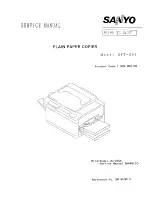
• Inputs to the DC Controller PCB (3/3)
Figure 3-110
Q1604
Q1605
Q1606
Q1607
Q1608
Q1609
DC controller PCB
Scanning lamp
intensity sensor
Drum ambient
temperature sensor
Toner sensor
Fixing main
temperature
detection
Fixing sub
temperature
detection
Pick-up unit PCB
15V -12V
J27
J26
J112
-1
-4
-2
FLS
-3
J105
-B10
-B11
5V
J117
-8
-7
-6
RTEMP
(analog
signal)
J108
-1
-2
J108
-3
-4
5V
Upper cassette paper
level detection 0
Upper cassette paper
level detection 1
Lower cassette paper
level detection 0
Lower cassette paper
level detection 1
Upper cassette
delivery detection
Lower cassette
delivery detection
TEP
TH1
TH2
UCSPD
LCSPD
1RPD0
2RPD0
1RPD1
2RPD1
J114
-5V
-A10
J114
-A11
J122
-1
J122
-3
J122
-2
J122
-4
TH
See p. 3-118
When the toner inside
the developing assembly is
below a specific level, '0'.
When Q1604 has detected
paper, '1'.
When Q1605 has detected
paper, '1'.
When Q1606 has detected
the lifter, '1'.
When Q1608 has detected
the lifter, '1'.
When Q1607 has detected
the lifter, '1'.
When Q1609 has detected
the lifter, '1'.
See p. 3-24
Detects the temperature
around the drum.
COPYRIGHT © 1996 CANON INC. CANON GP215/200 REV.0 JULY 1996 PRINTED IN JAPAN (IMPRIME AU JAPON)
3–12
3. OPERATIONS AND TIMING