


6
6
6-8
6-8
Trouble Shooting > Trouble Shooting Items > Adjustment of Fixing System > Nip-width Specifications
Trouble Shooting > Trouble Shooting Items > Adjustment of Fixing System > Nip-width Specifications
Misformed Image
Image is misformed
Cause
Solution
1) Poor contact exists to the connectors on the
laser scanner unit
Reconnect the connectors: J801 and J802
2) Poor contact exists to the connectors on the
formatter
Reconnect the connectors: J3 and J7
3) The laser scanner unit is defective
Replace the laser scanner unit.
4) The high-voltage power supply is defective
Replace the engine controller unit.
Repetitive Image Defects Ruler
Component
Distance
between
defects (mm)
Image defects
Dirt
Dropouts
Dirt on back
Loose toner
Registration roller
About 43
Primary charging roller
About 38
Photosensitive drum
About 75
Developing roller
About 42
Transfer roller
About 39
Fixing film unit
About 57
Pressure roller
About 63
■
■
F-6-15
F-6-15
T-6-13
T-6-13
T-6-14
T-6-14
Adjustment of Fixing System
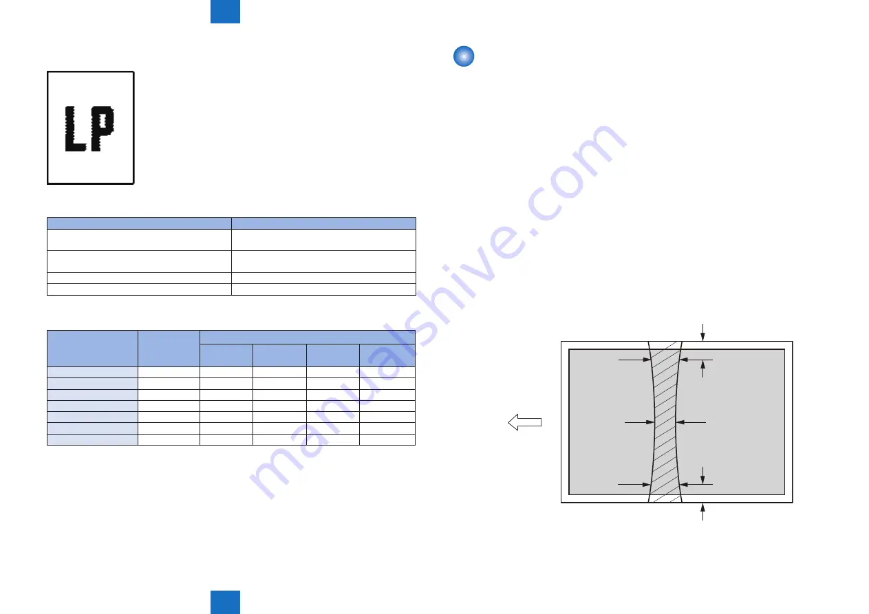
Nip-width Specifications
The nip-width of the fixing unit is not adjustable in this printer, however the improper nip-width
may cause the poor fixing.
Follow the procedures below to check the nip width.
1) Prepare an all-black print of letter size that is printed with the cartridge for this printer
before visiting the user.
2) Load the printed sheet facing UP in the printer cassette.
3) Open the face-up cover.
4) Print a test page.
5) Turn off the power switch when the leading edge of media comes out of the face-up
delivery slot.Wait for 20 seconds and turn on the power switch. Then open the jam removal
cover and pull the paper out.
6) Measure the width of the glossy band across the paper and check if it meets the
requirements below:
Center (a): 6 to 9 mm
Left (b): 6 to 9 mm
Right (c): 6 to 9 mm
c
b
a
15mm
15mm
Media feed direction
Center of
letter sized paper
■
•
•
•
F-6-16
F-6-16


