Chapter 12
12-33
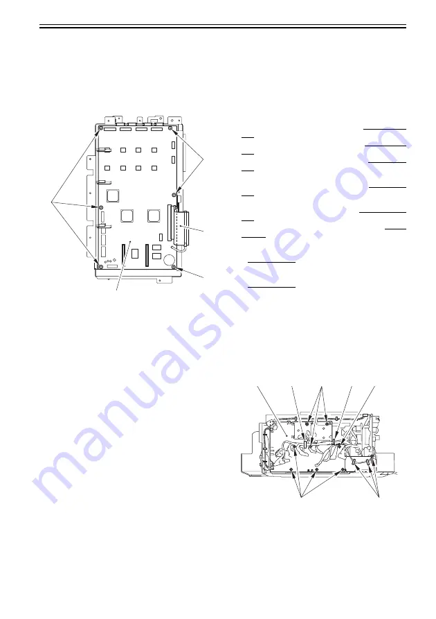
12.5.10.4 Removing the DC Controller
PCB1 (IMG)
1) Remove the DC controller PCB1 (DCCON IMG)
[3].
- 6 screws [1]
- 1 flat cable [2]
F-12-54
12.5.10.5 When Replacing the DC
Controller PCB
1) After replacing the DC controller PCB, use the
following service mode to initialize the memory
of the DC controller PCB:
COPIER>FUNCTION>CLEAR>DC-CON
2) Enter the settings indicated on the service label
using the following service mode:
COPIER>ADJUST>LASER>PVE-OFST
Use it to enter an adjustment value for the laser
beam position.
COPIER>ADJUST>FEED-ADJ>REGIST
Use it to adjust the timing at which the registration
roller clutch goes ON.
COPIER>ADJUST>FEED-ADJ>ADJ-REFE
Use it to adjust the horizontal registration for re-
pickup.
COPIER>ADJUST>CST-ADJ>MF-A4R
Use it to adjust the paper width basic value for the
manual feed tray.
COPIER>ADJUST>CST-ADJ>MF-A6R
Use it to adjust the paper width basic value for the
manual feed tray.
COPIER>ADJUST>CST-ADJ>MF-A4
Use it to adjust the paper width basic value for the
manual feed tray.
3) Turn off and then on the main power switch.
4) Select the following in service mode:
COPIER>FUNCTION>LASER>L-ADJ-0.
5) Press the OK key. (The machine starts auto
adjustment and will indicate 'END' at its end.)
12.5.11 Main Power Supply PCB
12.5.11.1 Preparation for Removing the
Main Power Supply PCB
1) Remove the rear fan cover.
Reference[Removing the Rear Fan Cover]
2) Remove the rear lower cover.
Reference[Removing the Rear Lower Cover]
3) Remove the IH power supply unit.
Reference[Removing the IH Power Supply
Unit]
4) Remove the DC power supply unit.
Reference[Removing the DC Power Supply
Unit]
5) Remove the relay PCB.
Reference[Removing the Relay PCB]
6) Remove the All-night Power Supply PCB.
Reference[Removing the All-night Power
Supply PCB]
7) Remove the DC/DC converter PCB (38V)
1.
Reference[Removing the DC/DC
Converter PCB (38V)1]
8) Remove the DC/DC converter PCB (38V)
2.
Reference[Removing the DC/DC
Converter PCB (38V)2]
12.5.11.2 Removing the Main Power
Supply PCB
1) Remove the main power-supply middle support
plate [3].
- 4 clamps [1]
- 8 screws [2]
F-12-55
[3]
[2]
[1]
[1]
[1]
[1]
[1]
[2]
[2]
[3]
[1]
[2]
Summary of Contents for Color imageRUNNER C4580
Page 22: ...Chapter 1 INTRODUCTION ...
Page 64: ...Chapter 2 INSTALLATION ...
Page 110: ...Chapter 3 BASIC OPERATION ...
Page 119: ...Chapter 4 BASIC OPERATIONS AS A PRINTER ...
Page 129: ...Chapter 5 MAIN CONTROLLER ...
Page 138: ...Chapter 5 5 8 F 5 8 CPU HDD ROM access to the program at time of execution ...
Page 165: ...Chapter 6 ORIGINAL EXPOSURE SYSTEM ...
Page 209: ...Chapter 7 IMAGE PROCESSING SYSTEM ...
Page 212: ...Chapter LASER EXPOSURE 8 ...
Page 239: ...Chapter 9 IMAGE FORMATION ...
Page 324: ...Chapter 10 PICKUP FEEDING SYSTEM ...
Page 435: ...Chapter 11 FIXING SYSTEM ...
Page 460: ...Chapter 11 11 23 F 11 13 SEN3 SEN2 SEN1 SEN2 SEN3 SEN1 SEN2 SEN3 SEN1 ...
Page 491: ...Chapter 12 EXTERNALS CONTROLS ...
Page 498: ...Chapter 12 12 5 F 12 2 FM1 FM7 FM9 FM2 FM13 FM14 FM12 FM11 FM10 FM5 FM3 FM4 FM8 FM6 ...
Page 512: ...Chapter 12 12 19 2 Remove the check mark from SNMP Status Enabled F 12 10 ...
Page 553: ...Chapter 13 MEAP ...
Page 557: ...Chapter 14 RDS ...
Page 569: ...Chapter 15 MAINTENANCE INSPECTION ...
Page 578: ...Chapter 16 STANDARDS ADJUSTMENTS ...
Page 597: ...Chapter 17 CORRECTING FAULTY IMAGES ...
Page 612: ...Chapter 17 17 14 F 17 7 PLG1 ELCB1 SP1 H4 H3 H2 H1 H1 H2 LA1 ...
Page 617: ...Chapter 18 SELF DIAGNOSIS ...
Page 644: ...Chapter 19 SERVICE MODE ...
Page 778: ...Chapter 20 UPGRADING ...
Page 823: ...Chapter 21 SERVICE TOOLS ...
Page 828: ...APPENDIX ...
Page 851: ......


