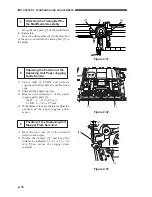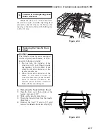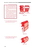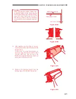
2-7
CHAPTER 2 STANDARDS AND ADJUSTMENTS
e. Adjusting the Image Read Start
Position (ADJ-XY)
1) Place the Test Sheet on the copyboard
glass.
2) Select ADJUST>ADJ-XY in service
mode.
3) on the ADJ-XY screen, press the Copy
Start key.
•
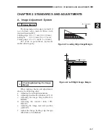
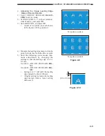
The appropriate copying mode will
automatically be selected, and a copy
is made with a shift of about 50 mm as
shown in the figure.
Figure 2-13
4) If part of the image is missing, decrease
the setting of ADJ-X, ADJ-Y in service
mode.
5) If part of the image is outside the image
area, increase the setting of ADJ-X, ADJ-
Y.
6) Press the Copy Start key once again, and
make a check.
7) Press the Reset key.
f.
Adjusting the Image Trailing Edge
Margin (TR-END-A, B; end of transfer
high voltage)
If you have replaced the transfer drum
unit in the field, correct the variation in the end
of the transfer voltage.
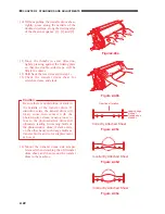
1) Select ADJUST>FEED-ADJ>TR-END-
A or B in service mode, and enter '25' (10
mm).
2) Select ADJUST>FEED-ADJ>TR2-ON;
then, press the OK key.
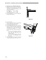
3) Measure the distance X (mm) between the
point at which blurring starts along the
trailing edge of the image on the
generated test print and the trailing edge
of the image.
4) Enter the result of (10 - x)/0.4 as the
adjustment value of TR-END-A or -B.
(Round the result up to a whole number.)
5) Select ADJUST>FEED-ADJ>TR2-ON in
service mode once again; then, press the
OK key.
6) Check to make sure that the image along
the trailing edge of the generated test print
is not blurred.
7) Record the value of ADJUST>FEED-
ADJ>TR-END-A or -B on the service
label.
ADJ-X
ADJ-Y
50
50
Figure 2-13a


