


<D
ISASSEMBLY AND
R
EASSEMBLY
N
OTES
>
• When the AF unit is removed, the position relative to the focusing screen must be
adjusted.
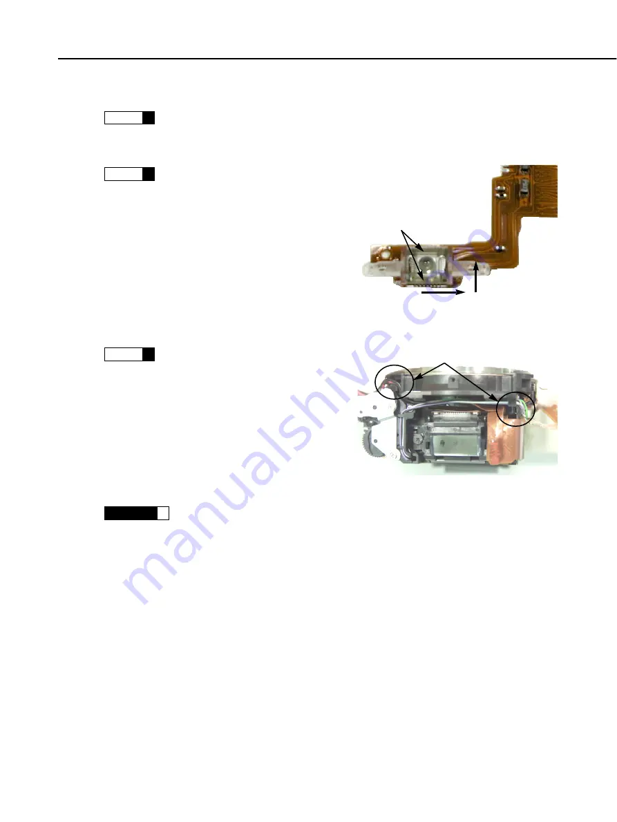
• If the TTL flex or TTL lens has been
removed for replacement, etc., eliminate
play by positioning it in the direction of the
arrows, then apply Diabond 1663G Black
on the top and bottom.
• As shown in the right figure, after setting
the contact plate and the phase board’s
lead wires, fix with Diabond 1663G Black.
Note that if you pull the contact plate’s lead
wires too much, it will not operate properly.
Be sure to check that the pins work.
• Check that there is no difference in exposure level before and after the focusing
screen replacement. If the difference is large, carry out the AE adjustment.
• To replace the focusing screen, unhook the both side of the focusing screen holder.
Be careful not to damage the focusing screen, and after replacement, check that
the focusing screen is assembled properly.
Part 3: Repair Information
3-17
: AF unit
1
NOTE
: Gluing TTL flex and TTL lens in place
2
NOTE
: Fixing the contact plate and phase
board lead wires in place
3
NOTE
: Focusing Screen Replacement
3
CAUTION
Fig. 3-27 TTL lens fixing
Apply Diabond 1663G Black
on the top and bottom
Eliminating TTL lens play
Fig. 3-28 Bottom of front panel
Lead wire fixing with
Diabond G Black
Summary of Contents for C12-8453
Page 7: ...Part 1 General Information ...
Page 12: ...Fig 1 2 Three External Views Part 1 General Information 1 5 ...
Page 53: ...Part 1 General Information 1 46 Fig 1 23 Three External Views ...
Page 67: ...Part 2 Technical Information ...
Page 103: ...Part 3 Repair Information ...
Page 104: ...This page intentionally left blank ...
Page 117: ... MEMO Part 3 Repair Information 3 13 ...
Page 123: ... MEMO Part 3 Repair Information 3 19 ...
Page 137: ... MEMO Part 3 Repair Information 3 33 ...
Page 148: ...Part 4 Electrical Adjustment ...
Page 195: ...Part 5 Parts Catalog ...
Page 196: ...This page intentionally left blank ...
Page 198: ......
Page 200: ......
Page 202: ......
Page 204: ......
Page 206: ......
Page 208: ......
Page 210: ......
Page 212: ......
Page 214: ......
Page 216: ......
Page 218: ......
Page 220: ......
Page 222: ......
Page 224: ......
Page 226: ......
Page 228: ......
Page 230: ......
Page 237: ...Part 6 Electrical Diagrams ...
Page 271: ......


