


Part 3: Repair Information
3-1
1. REPAIR PREPARATIONS
IMPORTANT! R
EAD THIS BEFORE STARTING REPAIR
1.1 B
LEED THE
M
AIN
C
APACITOR
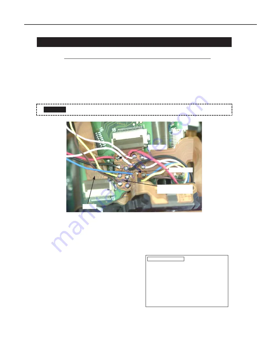
• As soon as you remove the front cover, be sure to drain the main capacitor with a
bleeder resistor of around 500 ohms, 10 W.
• The flash bleed points are at the soldered parts of XE-P (red) on the viewfinder flex
(EYE model) or VIA flex (NON-EYE model), and TRG-G (blue). See the figure below.
Fig. 3-1 Bleed points
1.2 F
LASH
C
HARGING
I
NHIBIT
M
ODE
You can use the adjustment software to set the camera to the flash charging inhibit
mode.
Flash charging inhibit mode setting
procedure:
Main menu
→
Self-Check menu
→
Select
Flash Charging Inhibit.
The screen on the right will then appear with
the flash inhibit mode set. The adjustment
software will exit automatically.
To cancel, select Flash Charging Inhibit again
or select Exit on the Main menu.
• Beware that it is a high-voltage circuit and prevent electrical shock.
CAUTION
FLASH_D
Flash Charging Inhibit
This sets the flash charging inhibit mode.
After the flash charging inhibit mode is set,
the adjustment software will exit automatically.
Before returning the camera to the user, be sure
to cancel the flash charging inhibit mode.
To cancel the flash charging inhibit mode, select
Flash Charging Inhibit again or select Exit
on the Main menu.
Press Return to set the flash charging inhibit mode.
To return to the Self-Check menu, press the space bar.
Fig. 3-2 Flash charging inhibit screen
Blue (TRIG-G)
Top flex
Red (XE-P)
Finder flex (EYE)
VIA flex (NON-EYE)
Summary of Contents for C12-8453
Page 7: ...Part 1 General Information ...
Page 12: ...Fig 1 2 Three External Views Part 1 General Information 1 5 ...
Page 53: ...Part 1 General Information 1 46 Fig 1 23 Three External Views ...
Page 67: ...Part 2 Technical Information ...
Page 103: ...Part 3 Repair Information ...
Page 104: ...This page intentionally left blank ...
Page 117: ... MEMO Part 3 Repair Information 3 13 ...
Page 123: ... MEMO Part 3 Repair Information 3 19 ...
Page 137: ... MEMO Part 3 Repair Information 3 33 ...
Page 148: ...Part 4 Electrical Adjustment ...
Page 195: ...Part 5 Parts Catalog ...
Page 196: ...This page intentionally left blank ...
Page 198: ......
Page 200: ......
Page 202: ......
Page 204: ......
Page 206: ......
Page 208: ......
Page 210: ......
Page 212: ......
Page 214: ......
Page 216: ......
Page 218: ......
Page 220: ......
Page 222: ......
Page 224: ......
Page 226: ......
Page 228: ......
Page 230: ......
Page 237: ...Part 6 Electrical Diagrams ...
Page 271: ......


