6
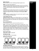
Detector reset (L+ when programmed for ID)
Some detectors require the removal of power to reset (such as Viper Plus®
or Smoke detectors). You can program the L+ terminal to be used as an ID
output using option 7-4. The L+ terminal should then be used as the
negative supply for these devices. The positive supply should be taken from
the AUX +.
Internal Sounders, Speakers, Strobe and Keyswitch Wiring
DETECTOR
RESET
External Sounder & Strobe
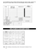
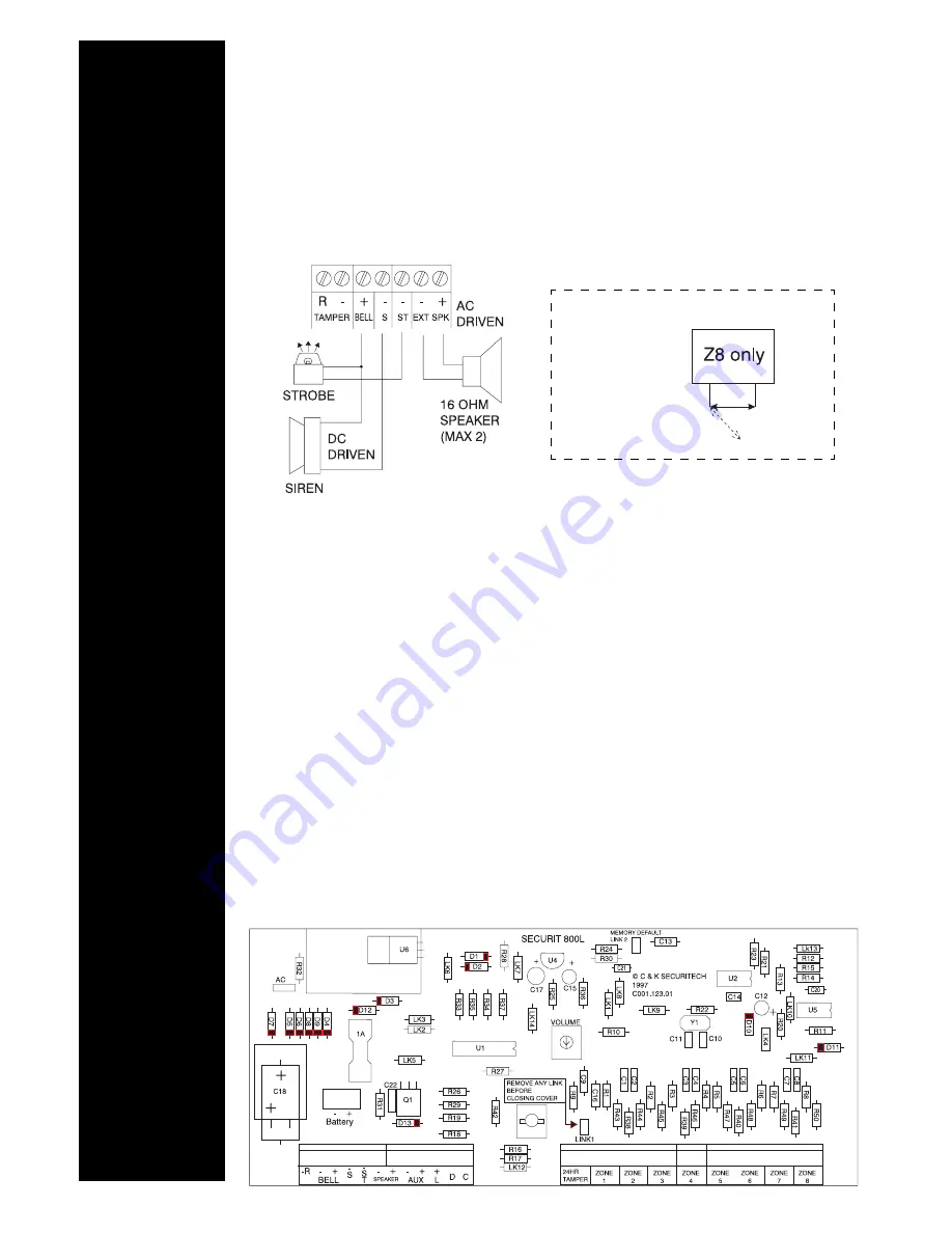
Diagram A shows the connection for external sounder and strobe. Please
note that the sounder trigger is applied negative (Negative ring).
ST-
Strobe switched negative trigger.
S -
Sounder switched negative trigger
+
Sounder hold off/strobe positive supply.
-
Sounder hold off supply & sounder tamper feed (negative).
-R
Sounder tamper return (negative).
AUX DC - Detector power
The auxiliary power is provided from connections marked AUX. This is to
provide the 12 V supply for detectors such as movement or glassbreak
detectors. The auxiliary power output is rated at 500 mA max (12 VCD
nominal). (See Diagram B.)
INTERNAL
DEVICES
EXTERNAL
DEVICES
AUXILIARY
POWER
BASIC BOARD
LAYOUT
Diagram B
Diagram A
Keyswitch Connections
Open
= ON
Closed = OFF
OFF
ON
A maximum of two 16 ohm speakers
may be fitted in parallel.


