background image

7

MOUNTING A REMOTE KEYPAD

1

Choose the keypad location, and then mark holes for mounting.

2

Make sure the cable is run through the backbox.

3

Screw the backbox in the selected position, making sure the cable is

not twisted.

WIRING A REMOTE KEYPAD

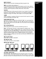
Use 6 core cable for connection of all remote keypads.

Connect the cable into the terminals shown in Diagram C, making sure each

wire goes to a like-named terminal in the panel. C goes to C, D to D, + to +

and - to -. Wire the tamper wires in series with your existing tamper loop.

You do not need to identify individual keypads to the system. If you use

more than one remote keypad, either wire it back to the control panel or

daisy-chain it from another keypad. Wire all connections in parallel with the

exception of the tamper circuit which you MUST


wire in series. (See the

Glossary for series and parallel examples.)

POWERING UP

INITIAL POWER UP

Note:

  Keep the lid off the main control panel in order to enter engineer

mode. Alternatively, you can enter 

7890 #

 to enter engineer mode.

1

Switch the mains supply ON. The internal sounder then starts.

This denotes a tamper alarm.

2

Enter 

1 2 3 4

 followed by the 

#

 (hash) button.  This silences the

sounder, and the TAMPER LED flashes.

This has now acknowledged and cancelled the alarm; however,

because either the panel or keypad lid is removed, your main tamper

loop is open. This is normal at this time.

3

Connect the battery and walk test the control panel.

This ensures all zones are clear.

4

Power Down and complete the wiring of the control panel.

NEVER wire the control panel live.

5

Power back up, cancel the alarm, and enter engineering mode by

entering 

7, 8, 9, 0

.

The panel is now ready for programming.

MOUNTING

REMOTE

KEYPADS

WIRING

REMOTE

KEYPADS

KEYPAD

DIAGRAM

INITIAL

POWER UP

Diagram C

Summary of Contents for SECURIT ST800L+

Page 1: ...INSTALLATION MANUAL SECURIT 800L CONTROL PANEL ST800L...

Page 2: ...mote Keypad 7 POWERING UP 7 Initial Power Up 7 PROGRAMMING 8 Exit Time 8 Entry Time 8 Sounder Duration 9 Night Set Home Set Exit Time 9 Circuit Programming 10 Extended Programming Options 10 Home Set...

Page 3: ...e the unit will be repaired and returned free of charge PRODUCT DESCRIPTION The Securit 800L is an 8 zone programmable microprocessor control panel using state of the art technology and manufacturing...

Page 4: ...eight 2 7 kg Excluding Battery Stand by Battery 7 0Ahr max valnve regulated lead acid Standby Time load dependent 24 hrs with 2 8Ahr nom 60 hrs with 7 0Ahr nom based on panel keypad 2 PIR 40 20 25 25m...

Page 5: ...corrected by a qualified electrician to ensure continued safe operation CAUTION Under certain circumstances the transformer metalwork can reach 70 C This is normal and well within prescribed limits B...

Page 6: ...hat the sounder trigger is applied negative Negative ring ST Strobe switched negative trigger S Sounder switched negative trigger Sounder hold off strobe positive supply Sounder hold off supply sounde...

Page 7: ...MUST wire in series See the Glossary for series and parallel examples POWERING UP INITIAL POWER UP Note Keep the lid off the main control panel in order to enter engineer mode Alternatively you can e...

Page 8: ...e lid of the panel or keypad PROGRAMMING Once the panel is in engineering mode the following options are available EXIT TIME 3 0 Range 10 90 seconds Enter 3 0 The factory default is 30 seconds You can...

Page 9: ...he selection The accept tone then sounds Note If extension speakers are fitted in Night and Home set you can alter the exit sounder volume by the control on the PCB marked VOLUME Option Option Results...

Page 10: ...ULL SET Turn and hold for 2 0 seconds PART SET EXTENDED PROGRAMMING OPTIONS 7 Range 1 8 The control panel offers the following additional options Enter 7 1 Disables sounder and strobe in Night Set Ent...

Page 11: ...subsequent alarms as well as isolated circuits First to alarm is shown by the LED being ON continuously Subsequent alarms are shown by the LED s flashing and isolated circuits are shown by LED s puls...

Page 12: ...code to prevent unauthorised alteration To enable this the engineer code must end in 9 If the engineer code is lost it will not be possible to enter engineer mode the PCB will need to be replaced Thi...

Page 13: ...m the exit time drops to 8 seconds as soon as the EXIT door has closed thus avoiding the preset exit time FULL SET KEYSWITCH Allows the panel to be set unset and reset through zone 8 Note The keyswitc...

Page 14: ...RY VOLTAGE V AUX VOLTAGE V INSTALLED BY SOUNDER CONNECTIONS CONTROL PANEL ST S R SONADE 2000 STROBE B D A T FLASHGUARD XL STROBE SIREN SUPPLY SUPPLY TAMPER OUT STARLIGHT 2000 ST R H H RTN ACTIVEGUARD...

Page 15: ...ne activates even in day mode Programmed to PA or FIRE Reprogram the zone to be an alarm zone or similar If you are still experiencing problems then contact our technical helpline with information at...

Page 16: ...STEMS is always endeavouring to improve quality and specification of all its products and may alter or amend this product and instructions without notice C K Systems Ltd Unit 24 Walkers Road North Moo...

Reviews: