


4 - 24D18C Drive Wheel Seal And Bearing Replacement
43
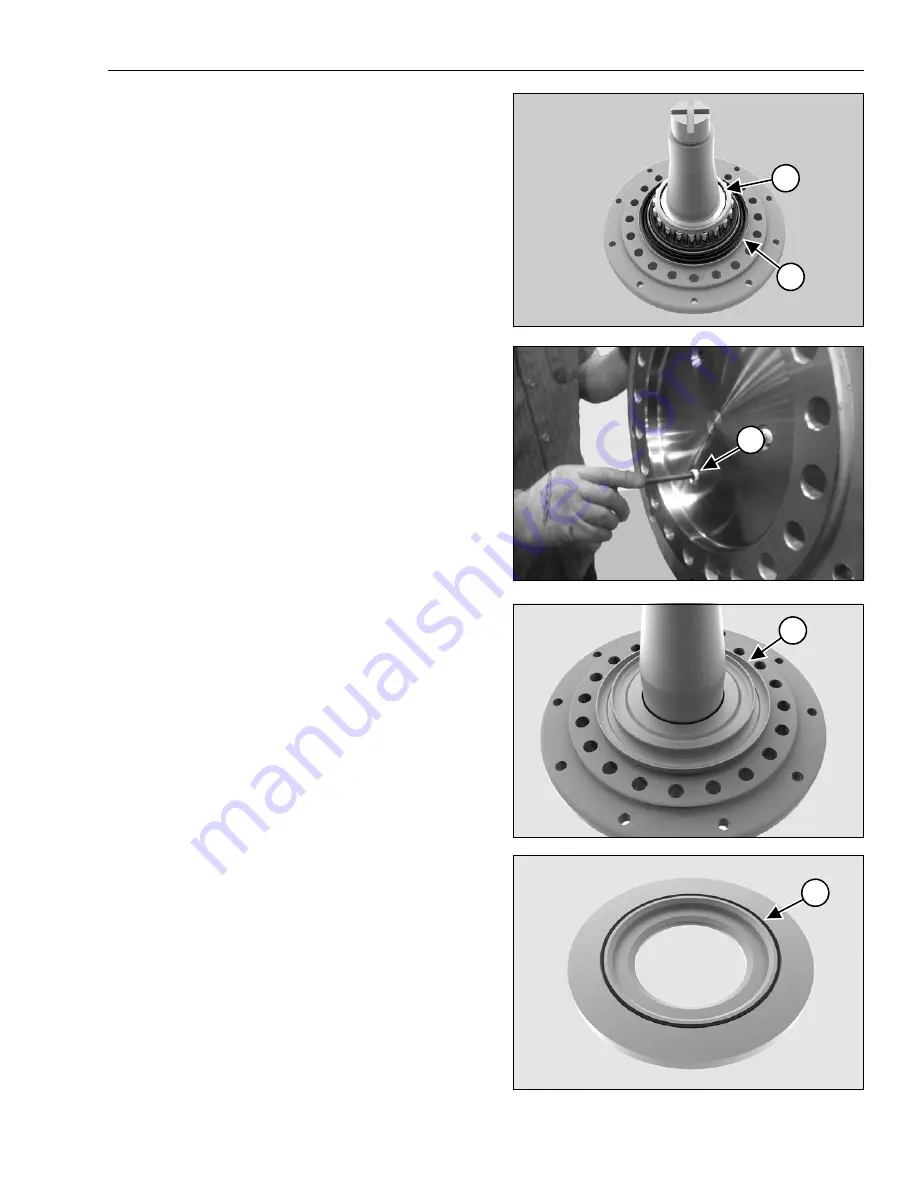
STEP 15
Remove the inner bearing cone (1) and the seal (2)
from the spindle.
NOTE:
On models before TRE0216003 the bearing
cone is press fit. Use a bearing splitter / puller to
remove the bearing or cut the bearing off the spindle.
Both methods can damage the seal shoulder and it
must be replaced.
NOTE:
On newer models remove the three plugs (3)
and install the three M14 pusher bolts, included with
the 2P-0080 Spindle Extraction Tool. Use the pusher
bolts to remove the bearing (1) and seal shoulder.
STEP 16
On older models, use a bearing splitter and puller to
remove the inner seal shoulder (1).
STEP 17
Remove the O-ring (1) from the inner seal shoulder.
Install a new O-r ing on the new 2C-3299-100
shoulder O-ring grove before installing the shoulder
in Step 18.
NOTE:
Apply clear petroleum jelly to the O-ring (1)
to hold it in place during assembly.
cp1021
1
2
cp1714
3
cp0521
1
cp0524
1
Summary of Contents for 24D18C
Page 2: ......
Page 4: ...2 Table Of Contents ...
Page 10: ...8 Required Tools And Capacities ...
Page 16: ...14 1 Track Removal And Installation ...
Page 22: ...20 2 Front And Rear Idler Wheel Seal And Bearing Removal And Installation ...
Page 28: ...26 2 Front And Rear Idler Wheel Seal And Bearing Removal And Installation ...
Page 34: ...32 3 Midroller Wheel Seal And Bearing Removal And Installation ...
Page 40: ...38 3 Midroller Wheel Seal And Bearing Removal And Installation ...
Page 54: ...52 4 24D18C Drive Wheel Seal And Bearing Replacement ...
Page 68: ...66 5 30 36D23 22MC Drive Wheel Seal And Bearing Replacement ...
Page 74: ...72 6 Tension Cylinder Removal And Installation ...
Page 105: ......
Page 106: ...camso co Camso 2015 ...