background image

0623 IH-10916VND

H-10916

OPERACIÓN (CONTINUACIÓN)

Procedimiento de operación antes de cada inicio

1.  Gire la perilla del regulador completamente en sentido contrario a las agujas del reloj (hacia la 

izquierda) para cerrar el flujo de aire. 

2.  Conecte la manguera de aire al tomacorriente del regulador.
3.   Coloque el interruptor encendido/apagado en la posición de apagado.
4.   Conecte el cable de alimentación.
5.   Coloque el interruptor de encendido/apagado en la posición de encendido y opere el compresor hasta 

que alcance la presión de apagado automático.

6.  Una la aguja o herramienta de caucho al extremo de la manguera.
7.  Ajuste el regulador a la presión adecuada para la herramienta o caucho. Siga las instrucciones para 

operar la herramienta.

Como el aire es vaciado desde el tanque con el uso de la aguja, herramienta de caucho, etc., el compresor 
se reiniciará automáticamente a su presión “de conexión” por defecto. Cuando se usa una herramienta 
continuamente, el compresor tendrá un ciclo automático de encendido y apagado.

 8.  Coloque el interruptor en la posición de apagado, desconecte el cable de alimentación y drene el 

tanque.

MANTENIMIENTO

Desconecte la fuente de alimentación y expulse toda la presión del sistema antes de intentar 
instalar, limpiar, reubicar o realizar otra función de mantenimiento. El servicio debe realizarlo un 

representante autorizado de servicios.

El compresor debe revisarse con frecuencia para ver si hay algún problema visible y se deben llevar a cabo 
los siguientes procedimientos de mantenimiento cada vez que se use el compresor.

Válvula de seguridad ASME

ADVERTENCIA: Use anteojos de 
seguridad. Revise la válvula de 

seguridad antes de realizar los siguientes pasos:

 1.  Encienda el compresor de aire y deje que el 

tanque se llene. El compresor se apagará cuando 
la presión llegue al máximo prestablecido.

 2.  Apague el compresor de aire.
 3.  Hale el anillo de la válvula de seguridad para 

liberar el aire por varios segundos. Use SIEMPRE 
su mano para desviar el aire a alta velocidad que 
pasa por su cara.

 4.  Suelte el anillo. El aire dejará de salir cuando 

suelte el anillo a aproximadamente 40 psi - 60 psi.

 5.  Si el aire se escapa después de haber soltado el anillo, o si se atasca la válvula y no puede manejarse 

con el anillo, retire de servicio la unidad. NO use el compresor de aire hasta que se haya reemplazado la 
válvula de seguridad. Usar el compresor de aire en 
esta condición puede causar la muerte o lesiones 
corporales graves.

Se debe reemplazar la válvula si no 
funciona o se escapa el aire después 

de soltar el anillo.

Drene el tanque

Con el compresor apagado y la presión liberada: 
Drene la humedad de los tanques abriendo la 
válvula de drenaje que está debajo de los tanques 
(Ver la Figura 5).

MANTENIMIENTO

 / REP

ARACION

IDENTIFICACION DE PROBLEMAS

OPERACION

MONT

AJE / INST

ALACION

SEGURIDAD /

ESPECIFICACIONES

PARA COMENZAR

Sp10

Figura 4

Figura 5

Válvula de drenaje

MAINTENANCE /


REP
AIR

TROUBLESHOOTING

OPERA

TION

ASSEMBL

Y /

 INST

ALLA

TION

SAFETY /


SPECIFICA

TIONS

GETTING ST

AR
TED

7

General Electrical Connections

WARNING: Risk of electric shock. Use GFCI. Use indoors only. Disconnect all connections before 
servicing. Use identical replacement parts. Servicing must be performed by a licensed, qualified 

electrician.

In the event of a malfunction or breakdown, grounding provides a path of least resistance for electrical 
current to reduce the risk of electric shock. This compressor is equipped with an electric cord having an 
equipment-grounding conductor and a grounding plug, as shown. The plug must be plugged into a 
matching outlet that is properly installed and grounded in accordance with all local codes and ordinances.

Improper connection of the equipment-grounding conductor can result in a risk of electric shock. The 
conductor with insulation having an outer surface that is green with or without yellow stripes is the 
equipment-grounding conductor. If repair or replacement of the electric cord or plug is necessary, do not 
connect the equipment-grounding conductor to a live terminal.

If the grounding instructions are not completely understood, or if you are in doubt as to whether the 
compressor is properly grounded check with a qualified electrician or service personnel.

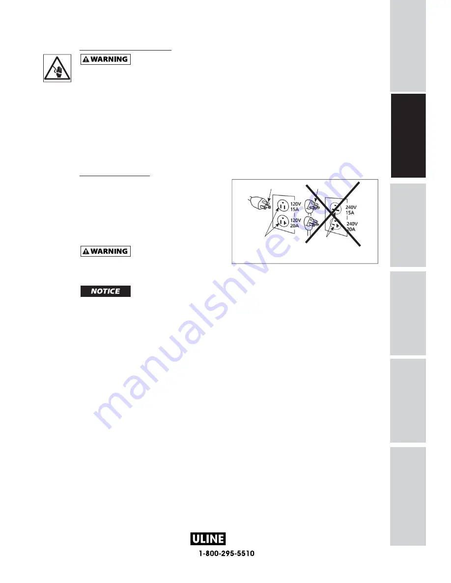
Grounding Instructions

1. This product is for use on a nominal 120 v circuit.

It must be grounded. In the event of an electric 
short circuit, grounding reduces the risk of 
electrical shock by providing an escape wire for 
the electric current. Unit is equipped with a cord 
that has a grounding prong. It will fit one of the 
common outlet types shown in Figure 3. If plug 
will not fit in the desired outlet, have the plug 
or the outlet replaced by a qualified electrician.

WARNING: Risk of electric shock. 

  Improper use of grounding 

plug can result in a risk of electrical shock. Plug must 
be plugged into an outlet that is properly installed and 
grounded in accordance with local codes and ordinances

NOTICE: Do not use grounding adapter.

2. Always check with a qualified electrician or serviceman if the grounding instructions are not completely 

understood, or if in doubt as to whether the product is properly grounded. Do not modify the plug
provided; if it will not fit the outlet, have the proper outlet installed by a qualified electrician.

3. Use only a 3-wire extension cord that has a 3-blade grounding plug, and a 3-slot receptacle that

accepts the plug on the product. Make sure your extension cord is not damaged. When using an
extension cord, be sure to use one heavy enough to carry the current your product draws. For lengths
less than  25ft. 16-3 AWG extension cords shall be used. An undersized cord results in a drop in the
voltage and loss of power and overheating. (NOTICE: Table 1 shows the correct size to use depending
on cord length. When in doubt, use the next heavier gauge. The smaller the gauge number, the
heavier the cord.)

4. Use of an extension cord may cause excess heat to motor. This could lead to tripped breaker (at 

electrical panel) or tripped thermal overload (on compressor motor). If this occurs, eliminate extension 
cord and plug compressor directly 

into electrical outlet. Avoid using extension cords; use longer air

hose(s) instead.

If repair or replacement of the cord or plug is necessary, do not connect the grounding wire to either flat blade terminal. 
The wire with insulation having an outer surface that is green with or without yellow stripes is the grounding wire.

Ground Pin

Ground Pin

Grounded Outlet

Grounded Outlet

CORRECT

INCORRECT

Figure 3 - Grounding Method

Summary of Contents for DC080500

Page 1: ...0623 IH 10916VND H 10916 8 Gallon Quiet Compressor Operating Instructions and Parts Manual Model DC080500 IN641800AV 5 16 2016 Campbell Hausfeld A Marmon Berkshire Hathaway Company EN...

Page 2: ...by observing all safety information Failure to comply with instructions could result in personal injury and or property damage Retain instructions for future reference REMINDER Keep your dated proof...

Page 3: ...anual please visit www campbellhausfeld com This is the safety alert symbol It is used to alert you to potential personal injury hazards The meaning of this safety alert symbol is as follows Attention...

Page 4: ...sed material pump spray guns filters lubricators hoses etc make up a high pressure pumping system the following safety precautions must be observed at all times 1 Read all manuals included with this p...

Page 5: ...e tank Make sure to drain tank regularly and inspect periodically for unsafe conditions such as rust formation and corrosion 15 Fast moving air will stir up dust and debris which may be harmful Releas...

Page 6: ...SPECIFICATIONS DC080500 Motor HP 1 0 Tank Capacity 8 gallon Phase Single Number of Cylinders 2 Air Delivery 90 psi 2 4 SCFM Voltage 110 120 Amperes 7 Hertz Cycles 60 Maximum Pressure 125 psi RPM 1750...

Page 7: ...ectrical line with the proper amps If other appliances operate on the same line they will reduce the available amps If the amperage is not adequate the result will be blown fuses or tripped circuits V...

Page 8: ...s ZERO by adjusting regulator knob fully counterclockwise before changing air tools or disconnecting air hose from outlet Tank Pressure Gauge Will show air pressure in tank while the compressor is run...

Page 9: ...ot fit in the desired outlet have the plug or the outlet replaced by a qualified electrician WARNING Risk of electric shock Improper use of grounding plug can result in a risk of electrical shock Plug...

Page 10: ...tion as the plug 3 The receptacles must be connected to circuits rated to carry at least the voltage and amperages shown 4 NEVER have a receptacle replaced with one of a higher amperage before determi...

Page 11: ...tomatic thermal protector that shuts off the motor if it overheats or has too much current This protector is a trip and hold protector To reset unplug the compressor and allow it to completely cool Th...

Page 12: ...illess type compressor requiring no lubrication End of Operation Storage 1 Turn Auto ON OFF switch to OFF position 2 Unplug power cord from wall outlet and wrap around handle to prevent damage when no...

Page 13: ...ector cuts out repeatedly 1 Low voltage 1 Check with voltmeter 2 Clogged air filter 2 Clean filter see Maintenance section 3 Lack of proper ventilation room temperature too high 3 Move compressor to w...

Page 14: ...0623 IH 10916VND H 10916 NOTES MAINTENANCE REPAIR TROUBLESHOOTING OPERATION ASSEMBLY INSTALLATION SAFETY SPECIFICATIONS GETTING STARTED 13...

Page 15: ...Repair Parts visit www campbellhausfeld com 24 hours a day 365 days a year Please provide following information Model number Serial number if any Part description and number as shown in parts list REP...

Page 16: ...UGE 1 8 NPT 1 5 IN DIA 1 17 CONNECT NPT 1 4 X 48 1 18 PRESSURE SWITCH 1 19 SAFETY VALVE 1 20 PLUG 1 4 NPT 1 21 CONNECT NPT 1 4 X 30 1 22 REGULATOR 1 23 OUTLET GAUGE 1 8 NPT 2 IN DIA 1 24 COUPLER 1 25...

Page 17: ...r Serial number if any Part description and number as shown in parts list REPAIR PARTS ILLUSTRATION FOR SR060510SV MAINTENANCE REPAIR TROUBLESHOOTING OPERATION ASSEMBLY INSTALLATION SAFETY SPECIFICATI...

Page 18: ...CON ROD 2 18 CON ROD SCREW M5 X 20 2 19 CROSSOVER TUBE 2 20 O RING FOR CROSSOVER TUBE 4 21 STATOR 1 22 ROTOR 1 23 BEARING 2 24 FRONT END BELL 1 25 BEARING 2 26 ECCENTRIC 2 27 ECCENTRIC SCREW M8 X 10 2...

Page 19: ...h installation and operation guidelines or damaged by contact with tools or surroundings b Pump or valve failure caused by rain excessive humidity corrosive environments or other contaminants c Cosmet...

Page 20: ...0623 IH 10916VND H 10916 Compresor silencioso de 8 galones Manual de Instrucciones y Lista de Piezas IN641800AV 5 16 2016 Campbell Hausfeld A Marmon Berkshire Hathaway Company Modelo DC080500 SP...

Page 21: ...SECHE Por favor lea y guarde estas instrucciones Lealas cuidadosamente antes de tratar de montar instalar operar o dar mantenimiento al producto aqui descrito Protejase usted mismo y a los demas obser...

Page 22: ...Si tiene preguntas o no entiende la informaci n presentada en este manual por favor visite www campbellhausfeld com Este es el s mbolo de alerta de seguridad Se usa para alertarle sobre posibles ries...

Page 23: ...tes utilizados bomba de material pistolas rociadoras filtros lubricantes mangueras etc forman un sistema de bombeo de alta presi n se deben cumplir las siguientes precauciones de seguridad en todo mom...

Page 24: ...ainer r guli rement le r servoir et d en faire une inspection p riodique quant aux conditions non s curitaires comme la formation de rouille et la corrosion 15 Le d placement d air rapide remuera la p...

Page 25: ...ICACIONES DC080500 HP del motor 1 0 Capacidad del tanque 30 28 L Fases Monof sico N mero de cilindros 2 Suministro de aire a 90 psi 68 l min Voltaje 110 120 Amperios 7 Hertz Ciclos 60 Presi n m xima 8...

Page 26: ...n la misma l nea reducir n los amperios disponibles Si el amperaje no es el adecuado har que los fusibles se quemen o que los circuitos se desconecten Voltios o voltaje Una medida de la fuerza de una...

Page 27: ...la perilla del regulador completamente en sentido contrario a las agujas del reloj antes de cambiar las herramientas de aire o desconectar la manguera de aire de la salida Medidor de presi n del tanq...

Page 28: ...sta calificado cambie el enchufe o el tomacorriente ADVERTENCIA Riesgo de descarga el ctrica El uso inapropiado de la clavija de conexi n a tierra puede causar un riesgo de descarga el ctrica El enchu...

Page 29: ...l enchufe 3 Los tomacorrientes deben estar conectados a circuitos con la capacidad nominal de surtir al menos el voltaje y amperaje indicados 4 NUNCA reemplace un tomacorriente con uno de mayor ampera...

Page 30: ...emasiada corriente Este protector es del tipo disparar y sostener Para reiniciarlo desconecte el compresor y permita que se enfr e por completo Esto deber a permitir que la sobrecarga autom tica se re...

Page 31: ...funcionamiento almacenamiento 1 Coloque el interruptor de ENCENDIDO APAGADO autom tico en la posici n de apagado 2 Desconecte el cable de alimentaci n del tomacorriente de la pared y enr llelo alreded...

Page 32: ...evise con un volt metro 2 Filtro de aire obstruido 2 Limpie el filtro vea la secci n de Mantenimiento 3 Falta de ventilaci n adecuada la temperatura de la habitaci n es muy alta 3 Mueva el compresor a...

Page 33: ...0623 IH 10916VND H 10916 MANTENIMIENTO REPARACION IDENTIFICACION DE PROBLEMAS OPERACION MONTAJE INSTALACION SEGURIDAD ESPECIFICACIONES PARA COMENZAR Sp13 NOTAS...

Page 34: ...w campbellhausfeld com 24 horas al d a 365 d as al a o Por favor proporcione la siguiente informaci n N mero de modelo N mero de serie si lo tiene Descripci n de la parte y n mero que le corresponde e...

Page 35: ...IELA 2 18 TORNILLO DE BIELA M5 X 20 2 19 TUBO DE FUSI N 2 20 ANILLO EN FORMA DE O PARA TUBO DE FUSI N 4 21 ESTATOR 1 22 ROTOR 1 23 RODAMIENTO 2 24 CAMPANA TERMINAL FRONTAL 1 25 RODAMIENTO 2 26 EXC NTR...

Page 36: ...llhausfeld com 24 horas al d a 365 d as al a o Por favor proporcione la siguiente informaci n N mero de modelo N mero de serie si lo tiene Descripci n de la parte y n mero que le corresponde en la lis...

Page 37: ...IELA 2 18 TORNILLO DE BIELA M5 X 20 2 19 TUBO DE FUSI N 2 20 ANILLO EN FORMA DE O PARA TUBO DE FUSI N 4 21 ESTATOR 1 22 ROTOR 1 23 RODAMIENTO 2 24 CAMPANA TERMINAL FRONTAL 1 25 RODAMIENTO 2 26 EXC NTR...

Page 38: ...b Falla de la bomba o v lvula causada por la lluvia exceso de humedad ambientes corrosivos u otros contaminantes c Defectos cosm ticos que no interfieran con la funcionalidad del compresor d Tanques o...

Page 39: ...23 IH 10916VND H 10916 e Compresseur silencieux de 30 L 8 gal Instructions d Utilisation et Manual de Pi ces Mod le DC080500 IN641800AV 5 16 2016 Campbell Hausfeld A Marmon Berkshire Hathaway Company...

Page 40: ...com Campbell Hausfeld 100 Production Drive Harrison Ohio 45030 Lire et conserver ces instructions Il faut les lire attentivement avant de commencer assembler installer faire fonctionner ou entretenir...

Page 41: ...ne comprenez pas l information pr sent e dans ce manuel visitez www campbellhausfeld com Ce symbole est une alerte la s curit Il sert vous avertir des dangers potentiels de blessure corporelle La sig...

Page 42: ...cautions de s curit suivantes doivent tre prises en consid ration tout moment 1 Lire attentivement tous les manuels inclus avec ce produit Familiarisez vous avec les commandes et l utilisation approp...

Page 43: ...ainer r guli rement le r servoir et d en faire une inspection p riodique quant aux conditions non s curitaires comme la formation de rouille et la corrosion 15 Le d placement d air rapide remuera la p...

Page 44: ...TECHNIQUES DC080500 Moteur HP 1 0 Capacit du r servoir 30 28 L tape Simple Nombre de cylindres 2 Pouss e d air 90 psi 68 l min Tension 110 120 Amp res 7 Hertz cycles 60 Pression maximale 862 kPa RPM 1...

Page 45: ...nsit appropri e Si d autres appareils fonctionnent sur la m me ligne ils r duiront l intensit disponible Si l intensit n est pas ad quate on causera le d clenchement des fusibles ou des court circuits...

Page 46: ...le bouton du r gulateur compl tement en sens antihoraire avant de changer d outil pneumatique ou de boyau air la sortie Manom tre du r servoir Pr sentera la pression d air dans le r servoir alors qu i...

Page 47: ...de remplacer la fiche ou la prise AVERTISSEMENT Risque de d charge lectrique Une mauvaise utilisation de la fiche de mise la terre peut causer un risque de d charge lectrique La fiche doit tre branch...

Page 48: ...tes avec lesquelles elle peut tre utilis e 2 Assurez vous que le produit est branch une prise ayant la m me configuration que la fiche 3 Les r ceptacles doivent tre branch s sur des circuits jaug s po...

Page 49: ...hement et maintien Pour r initialiser d branchez le compresseur et laissez le se refroidir compl tement Ceci devrait permettre la surcharge automatique de se r initialiser Le protecteur pourrait ne pa...

Page 50: ...sans huile n exigeant aucune lubrification Fin de l utilisation rangement 1 Placez l interrupteur marche arr t automatique OFF 2 D branchez le cordon d alimentation de la prise murale et enroulez le a...

Page 51: ...lenche r p tition 1 Faible tension 1 V rifiez avec un voltm tre 2 Filtre air bouch 2 Nettoyez le filtre voir la section d entretien 3 Manque d une ventilation ad quate temp rature de la pi ce trop lev...

Page 52: ...0623 IH 10916VND H 10916 ENTRETIEN R PARATION D PANNAGE UTILISATION ASSEMBLAGE INSTALLATION S CURIT CARACT RISTIQUES D MARRAGE DE L APPAREIL NOTES Fr13...

Page 53: ...de s rie s il y en a un Description et num ro de pi ce comme indiqu sur la liste des pi ces ILLUSTRATION DES PI CES DE REMPLACEMENT POUR LE DC080500 ENTRETIEN R PARATION D PANNAGE UTILISATION ASSEMBL...

Page 54: ...T 2 20 JOINT TORIQUE DU TUYAU DE RACCORDEMENT 4 21 STATOR 1 22 ROTOR 1 23 ROULEMENT 2 24 FLASQUE AVANT 1 25 ROULEMENT 2 26 EXCENTRIQUE 2 27 VIS EXCENTR E M8 X 10 2 28 VENTILATEUR DE REFROIDISSEMENT GA...

Page 55: ...s il y en a un Description et num ro de pi ce comme indiqu sur la liste des pi ces ENTRETIEN R PARATION D PANNAGE UTILISATION ASSEMBLAGE INSTALLATION S CURIT CARACT RISTIQUES D MARRAGE DE L APPAREIL...

Page 56: ...ACCORD 1 4 X 48 NPT 1 18 MANOSTAT 1 19 SOUPAPE DE S CURIT 1 20 BOUCHON 1 4 NPT 1 21 RACCORD 1 4 X 30 NPT 1 22 R GULATEUR 1 23 MANOM TRE DE SORTIE 1 8 NPT 2 PO DIA 1 24 COUPLEUR 1 25 CROU DE D CHARGE 1...

Page 57: ...ts corrosifs ou autres contaminants c Les d fauts cosm tiques n interf rant pas avec le fonctionnement du compresseur d Les r servoirs rouill s y compris mais non limit s la rouille en raison d un mau...

Reviews: