background image

31

11. Configuration

The SINEAX B 811 unit has to be opened before it can be
configured (see Section 8. “Withdrawing and inserting the
device”).

11.1 Switching output signals A1 and A12 between the

signal ranges 0…20 mA or 4…20 mA

The range of the outputs can be switched from
0…20 mA to 4…20 mA or vice versa depending on the
positions of jumpers J 202 and J 203 (Fig. 14).

Output signals

Pos. of jumpers

A1 / A12

J 202

J 203

4 … 20 mA

1

1

0 … 20 mA

3

3

11.2 Communication connector

Connect the communication connector to output A1 or
A12 (Figs. 10 to 13). Signals are then transferred in both
directions between the hand-held terminal and the
transmitter via the SINEAX B 811.

When using the field output A12, the 250 

 burden

connected across output A12 in the power supply unit
can be switched in and out of circuit with the aid of
jumpers J 204 and J 205 (Fig. 14).

Communication

Pos. of jumpers

connected to:

J 204

J 205

Field output A12*

Integrated 250 

 resistor

in circuit

the burden at measuring

output A1 is reduced 250 

Choise of A1 output signal
range 0/4 ... 20 mA
Voltage across A1 burden: 

10 V

Field output A12*

Integrated 250 

 resistor

not in circuit

the burden at

measuring output A1 is not reduced.

A1 output signal range
4 ... 20mA only
Voltage across A1 burden: 

15 V

Measuring output A1

Output signal range 4 … 20 mA
Voltage across A1 burden: 

15 V

*See “Measuring output” in the section “5. Technical
data”.

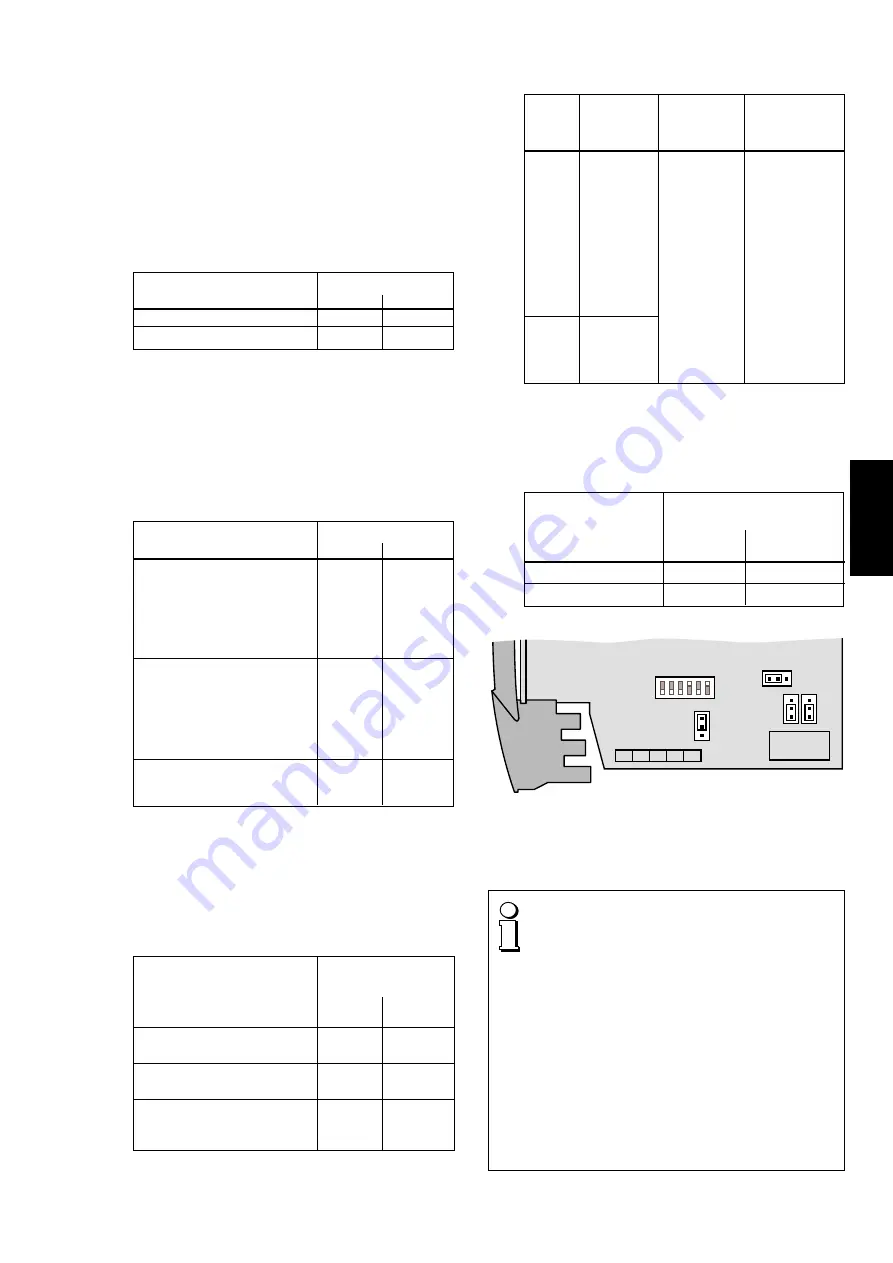
11.3 Response of the output signals A1 and A12 for a

fault in the measurement/supply circuit

The response of the output signals A1 and A12 can be
set with the aid of switches 1 and 2 on the DIP switch
S 201 (Fig. 3).

Response of output signals

Dip switch S 201

A1 and A12 for a short or
open-circuit of the measure-

Switch

Switch

ment/supply circuit

1

2

Linear
output signal
Increasing
output signal
Decreasing
output signal
(only with live zero signal)

S201

J202

1

3

1 2 3 4 5 6

ON

OFF

J203

J205

J204

1

3

1

3

Fig. 14. Positions of the DIP switches S 201 and jumpers J 202 to
J 205.

3

1

1

1

3

3

OFF

ON

OFF

OFF

OFF

ON

Break

Short-
circuit

Fault

Output

Output

Output

linear

driving

driving

behaviour

upscale

downscale

(with

live-zero

only)

Approx.

10% of full

scale end

value

e.g. 2 mA

with output

4…20 mA

or 1 V

with output

2…10 V

11.4 Response of the output contact AF for a fault in the

measurement/supply circuit

The response of the fault signalling relay can be set with
the aid of switches 3 and 4 on the DIP switch S 201
(Fig. 14).

Operating sense of

Dip switch S 201

the fault signalling
relay AF in the

Switch

Switch

event of a fault

3

4

Relay energised

ON

OFF

Relay de-energised

OFF

ON

Approx.

26 mA

with output

0/4…20 mA

0 mA

(with output

4…20 mA)

– 5 mA

(with output

0…20 mA)

Approx.

115%

of full

scale end

value

e.g. 23 mA

with output

0/4…20 mA

or

11.5 V

with output

0/2…10 V

The power supply unit must be capable of supplying
a brief current surge when switching on. The
transmitter presents a low impedance at the instant
of switching which requires a current I

Start

 of…

… I

Start 

approx. 250 mA for the version with a power

supply range 24 – 60 V DC/AC

or

… I

Start 

approx. 100 mA for the version with a power

supply range 85 – 230 V DC/AC

The red LED may also light briefly (< 1 s). The green
LED must light immediately.

The signal for indicating a failure in the measurement/
supply circuit is only enabled after a delay of typically
2.5 s. The output contact remains in its reset state
during the switch-on delay!

12. Commissioning

English

Summary of Contents for Gossen MetraWatt SINEAX B 811

Page 1: ...fon 41 56 618 21 11 Telefax 41 56 618 24 58 Telex 827 901 cbm ch Betriebsanleitung Speiseger t SINEAX B 811 Mode d emploi Source d alimentation SINEAX B 811 Operating Instructions Power pack SINEAX B...

Page 2: ...rativement tre observ s sont marqu s des symboles ci contre dans le pr sent mode d emploi Safety precautions to be strictly observed are marked with following symbols in the Operating Instructions Bet...

Page 3: ...AC 2 EEx ia IIC 3 24 60 V DC AC MSK eigensicher EEx ia IIC 4 85 110 V DC 85 230 V AC MSK eigensicher 3 Ausgangsgr ssen Messausg nge A1 und A12 0 5 V Rext 250 1 1 5 V Rext 250 2 0 10 V Rext 500 3 2 10...

Page 4: ...ereiche 0 5 bis 0 15 V bzw live zero 1 5 bis 3 15 V Kurzschlussstrom 40 mA Belastbarkeit UA1 UA12 20 mA Lastwiderstand UA1 UA12 UA V 20 mA Restwelligkeit 1 p p DC 10 kHz Gleichstromsignale IA Normbere...

Page 5: ...digitalen Kommunikations signale von und zu intelligenten Zweidraht Messumfor mern mit FSK Technik und Hart oder firmenspezifischem Protokoll Frequenzbereich 500 Hz 35 kHz 15 V 10 V IAN mA 0 3 V IAN...

Page 6: ...M ET RA W AT T CAM ILLE BA UER GOSS EN M ET RA W AT T CAM ILLE BA UER ON ON SINEAX B 811 ON GOSS EN M ET RA W ATT CAM ILLE BA UER GOSS EN M ET RA W ATT CAM ILLE BA UER 2 10 8 Ger t ffnen und schliesse...

Page 7: ...ssaufga be erforderlich sind mit denen auf dem Typen schild des SINEAX B 811 bereinstimmen Mess Speise Kreis Ausgang A1 A12 AF und Hilfsenergie H dass die Signaleingangs und Ausgangs leitungen als ver...

Page 8: ...ang Einzelheiten siehe Abbildung Relais HHT Hand Held Terminal H Hilfsenergie 3 13 8 4 14 9 5 15 10 1 6 2 7 MSK 3 13 8 4 14 9 5 15 10 1 6 2 7 Gr ne LED Betriebszustand Rote LED Leitungsbruch und Kurzs...

Page 9: ...sumformer Sicherer Bereich Explosions gef hrdeter Bereich X A1 A12 AF X Anschlussm glichkeit eines HHT1 Klemmen 2 und 7 galvanisch verbunden mit Klemmen 1 und 6 US H HHT1 Ex 1 6 2 7 5 4 3 13 14 9 10 8...

Page 10: ...reduziert sich die B rdenspannung an Ausgang A1 auf 10 V Eine digitale Kommunikation erfordert an Ausgang A1 eine minimale B rde von 250 Aus diesem Grund ist bereits im Speiseger t im Ausgangsstromkr...

Page 11: ...nd A12 bei Kurzschluss oder Schalter Schalter Bruch im Mess Speise Kreis 1 2 Ausgangssignal lineares Verhalten Ausgangssignal steigendes Verhalten Ausgangssignal fallendes Verhalten nur bei live zero...

Page 12: ...15 14 Mass Skizzen 146 5 17 5 120 0 5 0 Bild 16 SINEAX B 811 im Geh use S17 auf Hutschiene 35 15 mm oder 35 7 5 mm nach EN 50 022 aufgeschnappt 145 5 120 134 120 4 5 6 5 12 14 17 5 0 5 0 Bild 17 SINE...

Page 13: ...uisontautoris es travailler sur des installations techniques du r glage 2 Etendue de la livraison Fig 1 Source d alimentation 1 2 Etriers 2 pour ouvrir le bo tier 2 Plaquettes frontales 3 pour annotat...

Page 14: ...rs les sorties A1 et A12 peuvent tre configur es par le commutateur DIP afin d obtenir une sortie lin aire croissante ou d croissante Conforme toutes les exigences formul es dans la directive 89 336 C...

Page 15: ...munication est bidirectionnelle afin de permettre d une part la modification de la program mationduconvertisseurdemesure intelligent entechnique 2 fils et d autre part entre autres l interrogation des...

Page 16: ...e en moyenne annuelle 75 classe climatique standard 95 classe climatique accrue Vibration CEI 68 T2 6 2 g 5 150 5 Hz 1 octave min 2 h Choc CEI 68 T2 27 30 g 11 ms 7 Changement de la plaquette frontale...

Page 17: ...5 9 2 Montage sur paroi Tirer en dehors les languettes de fixation 1 en enfon ant en m me temps le bouton de verrouillage 4 voir Fig 6 gauche Pour rentrer si n cessaire les languettes de fixation il...

Page 18: ...HT El ment portable de communication Hand Held Terminal H Alimentation auxiliaire 3 13 8 4 14 9 5 15 10 1 6 2 7 MSK 3 13 8 4 14 9 5 15 10 1 6 2 7 Diode luminescente verte tat de fonctionnement Diode l...

Page 19: ...ils Enceinte s re Enceinte dangereuse X A1 A12 AF X Raccordement possible bien que peu usuel d un l ment portable de communication sur l entr e bornes 2 et 7 en parall le avec bornes 1 et 6 US H HHT1...

Page 20: ...e 11 2 Raccordement de communication Dans ce cas la sortie A1 peut tre charg e de la tension de charge totale de 15 V la place de des 10V Respecterenpluslesinstructionsderaccorde ment du syst me de co...

Page 21: ...rupture du circuit MSK 1 2 Signal de sortie lin aire Signal de sortie croissante Signal de sortie d croissante seulement en z ro flottant 3 1 1 1 3 3 D faut Sortie Sortie Sortie lin aire croissante d...

Page 22: ...ON ON Fig 15 14 Croquis d encombrements 146 5 17 5 120 0 5 0 Fig 16 SINEAX B 811 en bo tier S17 encliquet sur rail sym trique 35 15 mm ou 35 7 5 mm selon EN 50 022 145 5 120 134 120 4 5 6 5 12 14 17 5...

Page 23: ...t SINEAX B 811 Mode d emploi Source d alimentation SINEAX B 811 Operating Instructions Power pack SINEAX B 811 3 G O SS EN M ET R A W A TT C A M IL LE B A U ER SINEAX B 811 ON SINEAX B 811 ON G O SS...

Page 24: ...ncreasing or decreasing response The device fulfils the protection requirements of the EMC guidelines 89 336 EWG It bears the CE symbol for EMC 5 Technical data Input circuit MSK Signal range IE 4 20...

Page 25: ...tal signals with an intel ligent two wire transmitter designed for FSK and a HART or company specific protocol Frequency range 500 Hz 35 kHz 0 3 V IAN mA DC 15 33 AC 15 10 15 10 Standard non Ex Input...

Page 26: ...front of the device again This is done by inserting it behind the edge at the bottom and pressing it gently down and to the rear with the finger until it snaps into place right side of Fig 3 8 Withdra...

Page 27: ...m the front of the power pack see Figs 8 to 13 and can accommodate wire gauges up to max 2 5 mm2 Make sure that the cables are not live when making the connections The 230 V power supply and 250 V con...

Page 28: ...alling output Refer to the figure relay for details HHT Hand held terminal H Power supply 3 13 8 4 14 9 5 15 10 1 6 2 7 MSK 3 13 8 4 14 9 5 15 10 1 6 2 7 Green LED device standing by Red LED open and...

Page 29: ...4 20 mA 2 wire transmitter Safe area Hazardous area X A1 A12 AF X Connection of an HHT1 terminals 2 and 7 connected directly to terminals 1 and 6 US H HHT1 Ex 1 6 2 7 5 4 3 13 14 9 10 8 15 Input circu...

Page 30: ...changing the position of a jumper see Section 11 2 Communication connector The full burden voltage of 15 V is then available at output A1 insteadof10V Alsoobservetherulesforconnecting to the communic...

Page 31: ...201 Fig 3 Response of output signals Dip switch S 201 A1 and A12 for a short or open circuit of the measure Switch Switch ment supply circuit 1 2 Linear output signal Increasing output signal Decreasi...

Page 32: ...g 15 ON ON Fig 15 14 Dimensional drawings 146 5 17 5 120 0 5 0 Fig 16 SINEAX B 811 in housing S17 clipped onto a top hat rail 35 15 mm or 35 5 mm acc to EN 50 022 145 5 120 134 120 4 5 6 5 12 14 17 5...

Reviews: