background image

OPERATING AND USER MANUAL QUARTZ SERIES

33


Q-2A340

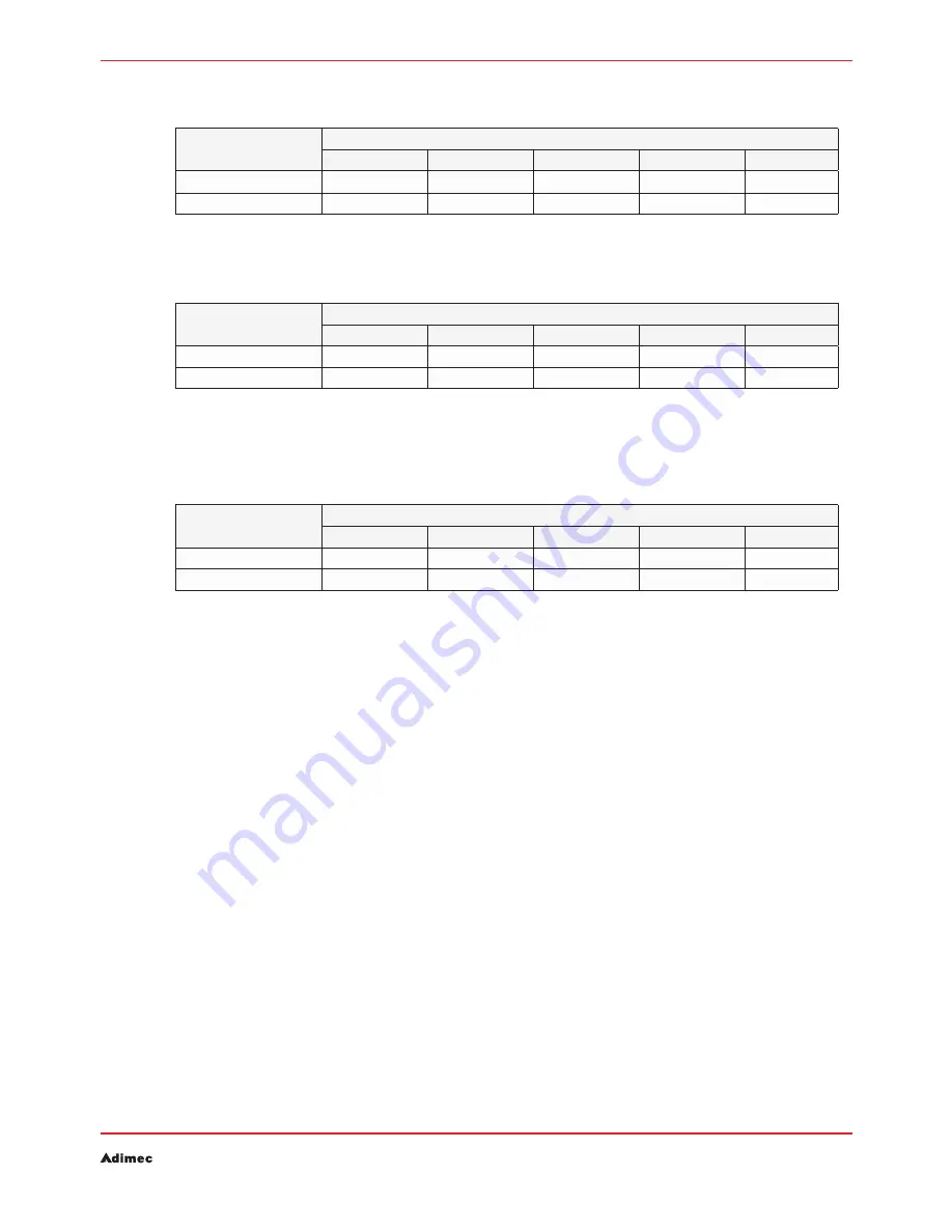
i/f clock [mhz]

taps

2

3

4

8

10

66

59

88

118

235

300

85

76

114

151

302

337

Q-12A340 max framerate

Table  7.3: 

Q-4A150 and Q-4A180

i/f clock [mhz]

taps

2

3

4

8

10*

66

31

47

62

124

159

85

40

60

80

160

180

Q-4A150 and Q-4A180 max framespeed

Table  7.4: 

* Not available in Q-4A150.

Q-12A65

i/f clock [mhz]

taps

2

3

4

8

10*

66

10

15

20

41

52

85

13

20

26

53

67

Q-12A65 max framespeed 

Table  7.5: 

Maximum frame speeds at different Camera Link interfaces in continuous mode for maximal resolution.

Control mode

7.3 

Three control modes are possible in the camera.  

If the Request mode is set to output the images immediately after acquisition (RQM0) and the 
acquisition trigger rate does not exceed the rate at which the CameraLink Interface configuration can 
output the images, the camera outputs the images normally.

Minimum frame periods (and corresponding trigger frequency) can be computed with the equations in 

section 7.1. As another reference the tables in section 7.2 may be used. 

Normal control mode

7.3.1. 

The control mode (MO1) is used in basic control applications. The state of CC1 determines start of 
integration and readout. 

Sync Control mode

7.3.2. 

In sync control mode (MO2), the start and stop of acquisition is controlled by the rising edge of CC1. 
The falling edge of CC1 does not trigger any event. The integration time is equal to the frame period. 
Sensor readout (image n) and sensor reset (image n+1) occur simultaneously at the rising edge of CC1 
when Request 

Summary of Contents for Q-2A340

Page 1: ...Operating and user manual QUARTZ SERIES CAMERA LINK MODELS...

Page 2: ...OPERATING AND USER MANUAL QUARTZ SERIES 2...

Page 3: ...ec s solutions add crucial competitive value to our customers high end systems and their applications as they yield brilliant results to the users of those systems The Netherlands based holding compan...

Page 4: ...amera control 20 6 CAMERA IDENTIFICATION AND CONTROL 23 6 1 Interface settings ICategory BootstrapCoaXPress 23 6 2 ICategory DeviceControl 24 6 3 ICategory ImageFormatControl 25 6 4 Image acquisition...

Page 5: ...OPERATING AND USER MANUAL QUARTZ SERIES 6...

Page 6: ...speed at full resolution 340 fps 2000 x 1088 CL 10 tap 156 fps 2048 x 2048 CL 8 tap 180 fps 2000 x 2048 CL 10 tap 65 fps 4080 x 3072 CL 10 tap Max burst speed at full resolution 340 fps 2000 x 1088 C...

Page 7: ...sible for incidental or consequential damages in connection with the furnishing performance or use of this material Layout composing and editorial staff Adimec Advanced Image Systems B V Illustrations...

Page 8: ...eep the CMOS sensor clean please take the following precautions Always keep the sensor cap in place as long as no lens is attached Remove the lens cap just before the lens is screwed on the camera It...

Page 9: ...due to loose particles and traces of oil or grease If this step does not result in an acceptable result continue with step 2 Remove the lensmount by unscrewing the 4 crosshead screws 2 that hold the l...

Page 10: ...eripheral equipment 2 2 6 For safety use an external SELV qualified power supply Maximum current 1 A For safety peripheral equipment must either be double isolated or SELV qualified Mounting Mechanica...

Page 11: ...OPERATING AND USER MANUAL QUARTZ SERIES 12...

Page 12: ...iguration Table 3 1 Q 2A340 Q 4A150 Q 4A180 Q 12A65 8 W 8 W 8 W 8 W Power consumption 12 Volt Table 3 2 NOTE The supply is reverse voltage protected When applying power to the camera with the wrong po...

Page 13: ...g I O connector Table 3 3 Mating cable connector Hirose type HR10A 7P 4P 74 NOTE The delay from non conductive to conductive state of the phototransistor is less than 1 5 s The delay from conductive t...

Page 14: ...ed For a description of the Camera Link interface please refer to the Camera Link specification NOTE PoCL Power over Camera Link is not supported When connecting the camera to a PoCL compliant frame g...

Page 15: ...me grabber application Connect the power cable to the camera and power up the camera with 12 Vdc Configure the framegrabber to 10 bit pixel depth resolution 2 taps interleaved and 85 MHz pixelclock Fa...

Page 16: ...nd frame grabber chain a test pattern generator is available The test pattern generator can also be enabled and disabled on demand Flat field correction allows for correction of shading This can be ca...

Page 17: ...he video data is mapped to the Camera Link ports The output resolution can be set to 8 bit or 10 bit by user command The output format can be set by user command The camera is equipped with a flash st...

Page 18: ...resulting data are transferred between the host system and the camera by means of a communication protocol The host system is the master in the communication link All actions are initiated by the host...

Page 19: ...e out period After not receiving an ACK or NAK character after the time out period has elapsed the host system must consider the transmitted message as not being received The time out time to be used...

Page 20: ...on error codes across vendors Common error text across vendors Strict well defined behavior of all functions in specification Openness to vendor specific error codes and text Ability to enumerate port...

Page 21: ...ll files and queries each one for its manufacturer name and port names This action produces a list of all possible ports The application can then select which port or ports it would like to communicat...

Page 22: ...uestion mark is a query command After the acknowledgement the camera sends the query value s for that command In case of more than one value the returned values are separated with a semicolon Values a...

Page 23: ...s the power up default settings The user may however change the power up settings without losing the factory default settings A copy of the factory default settings is stored in the camera The camera...

Page 24: ...ring always consists of 32 characters maximum If a string longer than 32 characters is set only the first 32 characters will be programmed Camera command set overview 6 4 Identification commands SYNTA...

Page 25: ...oty CCREQ Set image request trigger and polarity CCREQ Get image request trigger and polarity MO Set the acquisition mode 0 0 MO Get the current acquisition mode IT Set the integration time for contin...

Page 26: ...T VALUE CLC2 66 MHZ CLC3 85 MHZ FSE Enable flash strobe 1 1 FSE get flash strobe status FSP Set flash strobe polarity 1 1 FSP Get flash strobe polarity FSM Set flash strobe mode 0 0 FSM Get flash stro...

Page 27: ...put resolution 10 10 OR Get the current camera output resolution ROI Set the Region of Interest Full res Full res ROI Get the Region of Interest TPLVL Set uniform test pattern video level 511 511 TPLV...

Page 28: ...ct pixel list DPR Remove defect pixel DPT Defect pixel test mode enable 0 0 DPT Get defect pixel test mode BLCAL Calibrate black level FFCAL Preform flat field offset or gain calibration FFERR Get fla...

Page 29: ...OPERATING AND USER MANUAL QUARTZ SERIES 30...

Page 30: ...e from the sensor where the FOT is the Frame Overhead Time listed in the table above for the different sensors The time needed to output an image over the Camera Link interface Where FVALGap is the se...

Page 31: ...4080 x 3072 CL 10 tap Maximum framespeed in burst mode Table 7 2 Continuous mode 7 2 The continuous mode is the most basic mode of operation In continuous mode the camera captures images with an inte...

Page 32: ...tely after acquisition RQM0 and the acquisition trigger rate does not exceed the rate at which the CameraLink Interface configuration can output the images the camera outputs the images normally Minim...

Page 33: ...f the IT command Command format ITx Command format IT Return Message x where x is the integration time in units of 1 s The minimum allowed value for x is 1 and the maximum value allowed for x is 10000...

Page 34: ...ame period in the continuous mode When working in another mode the command is still available and the settings become active when the mode is set to continuous mode Acquisition trigger input polarity...

Page 35: ...The strobe can be switched on or off by means of the FSE command Command format FSEx Command format FSE Return Message x where x is set to 0 to disable the strobe output and x is set to 1 to enable th...

Page 36: ...h strobe timing 7 5 4 The strobe output timing can be programmed through the FST command Command format FSTx y Command format FST Return Message x y where x indicates the delay time between the sensor...

Page 37: ...mand format RQMx Command format RQM Return Message x where x indicates the Request Mode according to the following table x Request Mode 0 Images are output immediately after acquisition If acquisition...

Page 38: ...connector Request trigger selection Table 7 12 Parameter y sets the signal polarity y 1 request active on the rising edge y 0 request active on the falling edge Request size 7 6 5 The number of image...

Page 39: ...no longer be retrieved the number of images in memory is reset to 0 A Flush Buffer command clears the overflow error status Flush burst buffer 7 6 7 The image memory can be cleared by a flush buffer...

Page 40: ...r programmed but may not result in a reliable correction Correction is done by interpolation of the adjacent pixels according to the methode illustrated in figures 8 1 and 8 2 Defect pixel correction...

Page 41: ...removed from the defect pixel list by means of the DPR command Command format DPRx y Where x and y are the origin 1 1 base coordinates of the defect pixel If the coordinate does not exist in the list...

Page 42: ...evel to the set value Enabling black level calibration 8 2 1 The calibration requires a dark scene Command format BLCAL Set Black level only for monochrome 8 2 2 In monochrome cameras the average blac...

Page 43: ...urthermore for gain corrections local or global correction may be applied In local gain correction a particular pixel is flat fielded with respect to it s near environment In global gain correction th...

Page 44: ...may take a few milliseconds Termination is completed if FFSTA returns 0 1 Perform a full dark field offset calibration based on multiple images This calibration requires a dark scene Furthermore no sp...

Page 45: ...tatus according to the following table DEFINITION 0 No error 1 Starting a calibration action while a calibration is still pending 2 Non volatile storage CRC error during read of flat field data 100 Ra...

Page 46: ...ion 8 3 9 The result of a stored calibration can be retrieved Command format FFLCn Return Message n Where n 0 indicates the offset reference image n 1 4 indicate one if the available gain calibrations...

Page 47: ...bration Save brightfield done FFSTA wait Start Automatic exposure adjustment Set target exp level between x 50 1023 FFP103 x Tune video level between 50 1023 DN Start brightfield calibration FFCAL3 Sa...

Page 48: ...r by selecting a Region of Interest A user programmable output look up table can be configured to translate each pixel value to a user defined value This can be useful to implement for instance a Gamm...

Page 49: ...ra Command syntax WB Reply message r g b Where r g b are as above NOTE The total gain per color can not be greater that 32x So the product of digital gain par 9 2 3 and white balance gain is clipped t...

Page 50: ...mand format OR Return Message x where x is 8 or 10 indicating number of bits NOTE The 3 8 and 10 tap Camera Link formats only supports 8 bit pixel resolution If the camera is operated in eirther 3 8 o...

Page 51: ...e Q 12A65 this is 4080 pixels NOTE In case of a color camera the values of t and h will be rounded down to the nearest multiple of 2 rows NOTE In case of the Q 12A65 camera the values of t and h can o...

Page 52: ...HARGE CORRESPONDING WITH FULL SCALE CAMERA OUTPUT KEL 1 1 1x 1x 13 5 1 2 1x 2x 27 1 4 1x 4x 54 2 1 2x 1x 27 2 2 2x 2x 54 2 4 2x 4x 108 4 1 4x 1x 54 4 2 4x 2x 108 4 4 4x 4x 216 Theoretical charge value...

Page 53: ...and Vlow1 in figure 9 2 correspond to pixel reset and normal single slope sensor charge capacity respectively The levels Vlow2 and Vlow3 are added in multislope The red and blue line illustrate the ef...

Page 54: ...multislope response curve Figure 9 3 Vhigh Vlow3 Vlow2 Vlow1 Total exposure time Exposure kneepoint 2 Exposure kneepoint 1 Pixel reset Pixel sample Pixel with bright illumination Pixel with low illumi...

Page 55: ...exposure steps is set as a percentage of the total IT Command format MSTx y Command format MST Return message x y In case of 3 slopes y must exceed x Else an error will occur In case of 2 slopes and...

Page 56: ...table should be closed This is done through the OLUTEND command Command format OLUTEND If the camera did not receive exactly 1024 entries error 122 is issued and the OLUT status is reset Output look...

Page 57: ...red acquisition timing In this case the LVALgap is pushed to the minimum time possible This may be the case when running the camera with a small ROI width together with an 8 or 10 tap Camera Link inte...

Page 58: ...xel resolution If the camera is operated in eirther 8 or 10 tap Camera Link configuration the output resolution OR is pushed to 8 bit If the camera output is set to 10 tap operation the Lval gap size...

Page 59: ...10 tap implementation Command format TTFx Command format TTF Return Message x Where x indicates the interface speed x 1 equals implementation according table 12 1 refer to chapter 12 x 2 equals imple...

Page 60: ...t executed command The ERR command itself when executed successfully does not effect the last error result A list of all possible error values and the cause of the error code are shown below CODE CAUS...

Page 61: ...g The camera will continue working in the selected mode but instead of the usual image an artificial image is displayed The test pattern is built in for service and calibration purposes NOTE This imag...

Page 62: ...10 1 The exact gray levels expressed in 10 bit output are as presented on the next page For 8 bit output resolution the values are truncated as follows 10 BIT 8 BIT 0 0 1 0 2 0 3 0 4 1 15 16 511 127...

Page 63: ...and distance remain the same The ROI output image has the contour lines white and middle gray in the outer pixels Border pattern 0 1 2 3 4 H 4 0 1 2 3 4 W 4 W 3 W 2 W 1 W 1023 511 0 H H 3 H 2 H 1 H T...

Page 64: ...at field correction is enabled the output will reflect the local gain within the image The video level for test pattern 3 can be configured with command Command format TPLVLx TPLVL where x is the vide...

Page 65: ...16 Value pixel 4 2 24 The counter range is therefore 0 2 32 When the counter reaches the upper range limit it will roll over to 0 and count up from there Command format OVLx Command format OVL Return...

Page 66: ...OPERATING AND USER MANUAL QUARTZ SERIES 67...

Reviews: