L N L1T L2T CT VS VF
U V W E EX
26V 17V 0 10 11
TS 1 2 3 3P 4 5 7 2 CX CY C7 C8 2 A B + E D FC FA F
RSE
RSE
CX CY C7 C8 2 A B + E D FC FA F
UTP CAT 5
1 2 3 4
CX CY C7 C8 2 A B + E D FC FA F
1 2 3 4
p.
2
1
2
1
- M
anu
al
:
F
A
0
11
3
0
-E
N
F
A
0
113
0
-E
N
- 0
4
/2
0
18 - © C
A
M
E S
.p
.A
. - T
hi
s manu
al
's
c
onte
nts ma
y b
e e
d
ite
d at any time with
out n
oti
ce
.
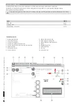
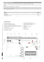
Memory Roll
Memory Roll Card
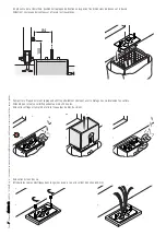
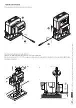
For memorizinguser and system configuration data, then using them on another control board.
After memorizing the data, it is best to remove the Memory Roll card while the control board is in operation.
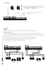
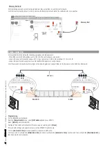
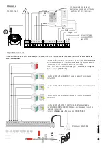
PAIRED CONNECTION
Important! Start by doing the following operations on both operators:
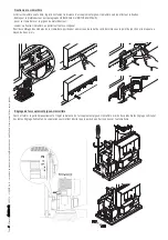
- fit the RSE card (with DIP-switches set to OFF) into the control board's connector;
- connect the two control boards using a CAT 5-type cable (max. 1,000 m) to terminals 2-2 / A-A / B-B;
- connect the control and safety devices onto the MASTER operator's control board.
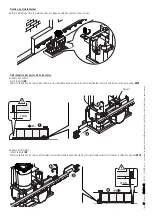
If the system fits sensitive safety-edges on the SLAVE gate-leaf, connect them to the terminals on the SLAVE control board.
Programming
For the MASTER control board:
from the
[Adjustments]
menu, select
[NET address]
and press ENTER.
Select
[Master]
and press ENTER.
Configure the SLAVE control board in the same way by selecting item
[Slave].
Proceed with settings and adjustments only on the MASTER control board.
The
[Automatic Clos.]
function should be activated on both cards
.
If you wish to activate the
[Maintained Act.]
function, deactivate the
[Automatic Clos.]
function and then activate the
[Maintained Act.]
function on both control boards.
MASTER
SLAVE

