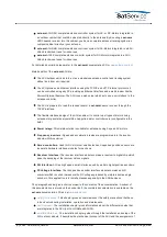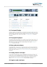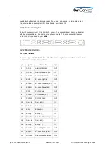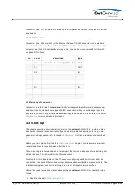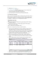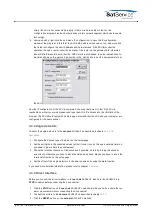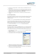
sat-nms ACU19V2 Front panel view
sat-nms ACU19V2 rear view
No.
component
No.
component
1
frontpanel display
6
alarm interfaces
2
frontpanel Keyboard
7
remote interfaces
3
drive cabinet interfaces
8
mains input
4
analog beacon level input
9
serial interface angle display
5
angle encoder interfaces
10
{}
The Display together with the keyboard is your interface for local operation without using e.g. an
external computer. It shows all of the desired parameters and gives a quick overview to the actual
state of your sat-nms ACU19V2. Please refer to chapter
6 Frontpanel Operation
for detailed
informations.
The keyboard together with the display is your interface for local operation without using e.g. an
external computer. Besides the keyboard you find 3 LEDs that show the actual state of the ACU-
RMU (fault state / limit switch state / motor movement) Please refer to chapter
6 Frontpanel
Operation
for detailed informations.
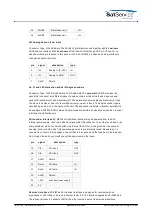
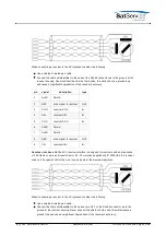
The sat-nms ACU19V contains a Vertex / General Dynamics Satcom Technologies Model 7200
compatible drive Interface. This interface commands the external driver unit to move the antenna
in 3-axis. Please refer to chapter
Interfaces to the antenna/Pin descriptions
for more detailed
informations.
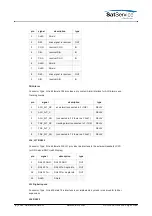
For connecting a third party beacon receiver, the sat-nms ACU19V provides an analog 0-10V
interface input. If you use a sat-nms LBRX beacon receiver, the level informations as well as the
beacon frequency and alarm bits are transmitted by UDP packages via http. Please refer to
chapter
Interfaces to the antenna/ Pin descriptions
for more detailed informations.
(C) 2022, SatService GmbH
www.satnms.com
ACU-19V2-UM-2209 Page 8/65


