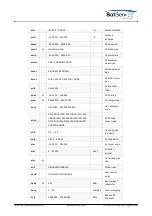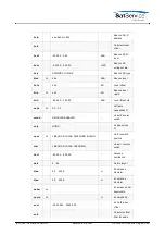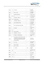
Azimuth / Elevation / Polarization
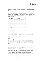
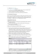
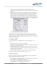
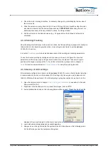
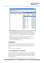
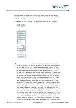
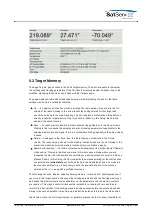
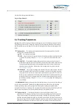
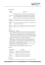
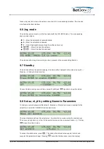
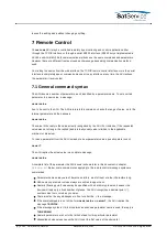
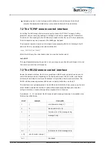
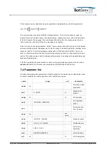
The Azimuth / Elevation / Polarization sections contains the parameters which are specific to the
individual axis. They are the same for each axis.
Parameter Name --- Description
Antenna diameter --- Set this parameter to the dish diameter. Units with the tracking function
installed use this value to estimate some tracking parameters. With offset antennas, the
diameter settings are different for the azimuth / elevation axes. This lets the ACU calculate
suitable tracking step sizes individually for each axis.
Step delta --- This parameter defines size of a step the antenna moves when you click to the
arrow buttons on the ACU main page. If you are using the arrow buttons to fine-tune the
antenna pointing manually, the best value is the pointing hysteresis described below. This
lets you move the antenna the smallest possible step when you click to an arrow button. For
special applications however it might be helpful to set the step delta to a much greater value.
Position sensor type --- With this parameter you set the type of position sensor the ACU shall
read for this axis. Principally, the ACU is capable to read SSI, RESOLVER and ANALOG type
position sensors. The selected sensor type must match the type of interface board installed
in your ACU. It is not possible to switch from SSI to RESOLVER or vice versa without
changing the interface module.When selecting a SSI type position encoder, also the number
of bits and the encoding scheme must be selected. For the position sensor type parameter
these values are combined to one name. E.g. 'SSI-13G' means 13 bit, Graycode SSI sensor,
'SSI-24B' means 24 bit binary encoded SSI sensor.Beside the SSI-xxX, RESOLVER and
ANALOG selections this parameter offers the choice 'NONE' which tells the ACU not to read a
position encoder at all. With this selection you can tell the ACU if the polarization is not to be
controlled by the ACU.If you are using multiturn SSI encoders you will have to scale the
reading (See 'Calibration scale' below).
Pre scale offset --- The pre-scale calibration offset is added to the raw position encoder
reading before scaling is applied. The pre scale offset is defined as an 8-digit hexadecimal
value in normalized position encoder ticks (00000000-FFFFFFFF equivalent to the full range
of the encoder (0-360° with single turn encoders).The pre scale offset must be adjusted to
avoid any 7FFFFFF to 8000000 overflow within the used range of the encoder. The value is
added to the encoder reading, neglecting an overfly eventually occurring. Thus, the offset
implements a 360° turnaround automatically.The pre scale offset may be computed and set
manually or by assistance of the ACU's automatic calibration function as described below.
Post scale offset --- The post scale calibration offset is added to the position value before
the angle value is displayed, but after the scaling is applied. The post scale offset is defined
in degrees of AZ/EL/POL.The ACU provides a function to calculate and set both, the pre-
scale and the post-scale offset from a known pointing:
1. Set the calibration scale / gear ratio for the axis (this calibration parameter is described
with the next paragraph).
2. Set the soft limits of the axis to preliminary values. In most cases this needs not to be
very accurate, the ACU needs this information to calculate the pre-scale offset to shift
the encoder overflow outside the used range.
3. Optimize the satellite pointing for the reception from a satellite for which the azimuth and
elevation values are known.
4. Click to the 'calc' label beside the calibration offset.
5. Enter the known pointing angle for the satellite and click to submit.
6. The ACU calculates and sets the calibration offsets to a value so that the actual pointing
is displayed as the angle you entered.
(C) 2022, SatService GmbH
www.satnms.com
ACU-19V2-UM-2209 Page 28/65

