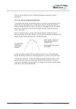
recently evaluated peak position.
The usage of the smoothing function is recommended when tracking satellites where the antenna
pointing oscillates less than 25% of the antenna's 3dB beamwidth. For tracking inclined orbit
satellites, the usage of smoothing may be problematic as such satellites may require an
significant position oscillation at 12 hours cycle time (sin 2wt). The smoothing function uses a
simple sinusoidal model which does not provide this double frequency component. Hence,
applying the smoothing function for such a satellite with more than 3 hours smoothing time may
average the antenna movement path too much.
The behavior of the satellite step track is adjustable with a couple of parameters. This permits to
tune the step track performance for special preconditions arising from the antenna and also the
satellite. The first parameters listed below are setup parameters, they are set once for an ACU
installation to adapt the ACU to the antenna and the beacon receiver.
AZAntennadiameter ELAntennadiameter --- The diameter values are used by the ACU
software to evaluate the antenna's beamwidth. There are separate values for both axes to
handle offset antennas as well.
BeaconRXtype --- With this parameter you specify which type of beacon receiver. For a
sat-nms LBRX beacon receiver set it to 'SATNMS' and set the receiver's IP address
accordingly. To make ACU and beacon receiver work together you should take care of the
following:
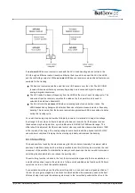
ACU and beacon receiver must be connected to the same Ethernet segment.
Both devices must have assigned IP addresses in the same subnet.
The LBRX beacon receiver must be configured for the correct LO frequency. The
displayed receive frequency must be the true RX frequency rather than the L-band
frequency.
At the sat-nms LBRX the ACU's IP address must be set as the 'UDP destination
address'.
The setting 'VOLTAGE' is used with any other type of beacon receiver or with a sat-nms LBRX
beacon receiver which has no TCP/IP connection to the ACU.When operating in SATNMS mode,
the ACU will automatically determine the beacon frequency from the sat-nms beacon receiver.
Also the beacon receiver's background activities like frequency tracking and noise reference
measurements get synchronized to the step track sequence in this mode. These features are not
available in the VOLTAGE operating mode.
BeaconRXIPaddress --- You need to enter the beacon receiver's IP address in 'dotted
quad' notation here if the receiver tape is set to 'SATNMS'.
BeaconRXvoltagescale BeaconRX0Vlevel --- These parameters define the slope and
offset of the beacon level voltage. The values must be set to match settings of the beacon
receiver. With the sat-nms LBRX beacon receiver you can set these parameters there as
well, chapter
'8.3.2 ACU And Beacon Receiver'
explains how to find the best settings for this.
The parameters in the table below are to be set individually for each satellite. They are set at the
'Tracking' page and stored with each target memory.
BeaconRXfrequency --- This parameter is only of interest if a third party beacon receiver
is used. The beacon frequency (you must enter the frequency received by the antenna
[MHz], not the IF frequency seen by the receiver.) is used by the ACU to calculate the
antenna's beamwidth and an approximated beam pattern. With the sat-nms LBRX beacon
(C) 2022, SatService GmbH
www.satnms.com
ACU-19V2-UM-2209 Page 57/65

