9
Actuation relays
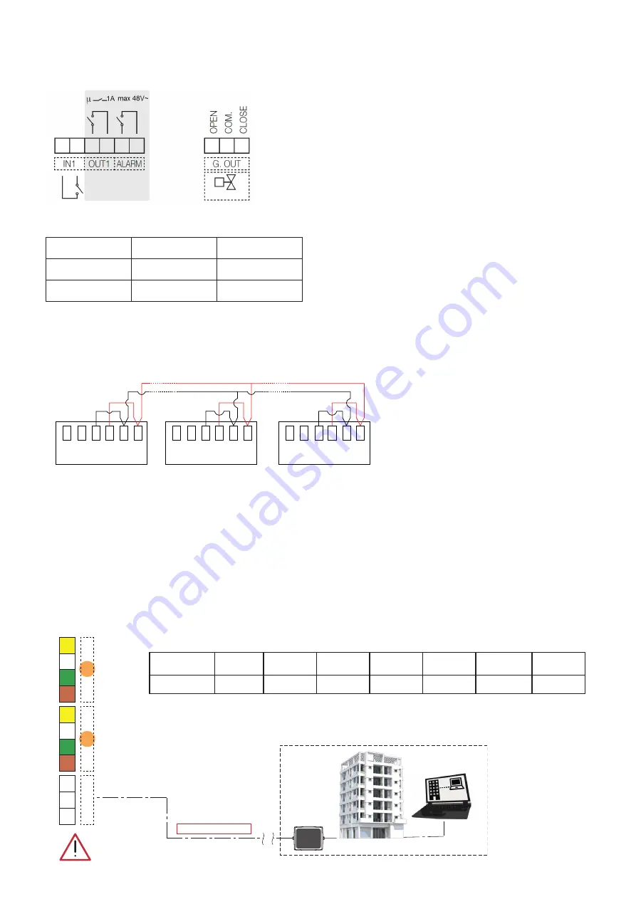
The board features the auxiliary replay contacts used to control auxiliary equipment and alarms.
IN1
input relay for voltage free contact. When the contact is closed, strainer
cleaning is inhibited
OUT1 relay output N.A. The contact closes when the strainer is in the cleaning
phase (max 48V,1A)
ALARM relay output N.A. for alarms indication (48V, 1A max)
G. OUT output for control of cold water injection valve on drain (max 5(2)A 250V).
The relay can drive a motorised diverter valve with 3-contact command.
MAINS LOSS
SIGNAL ACTIVE
OUT1
Open
Closed
ALARM
Open
Closed
Operation in parallel
Two or more strainers can be connected in parallel to increase the filtration capacity of the system, in cases in which there is no bypass provided
and the application calls for continuous service. Make sure however, that the cleaning phase does not occur at the same time. For this reason, if it is
detected that another device connected to the strainer is in the active phase, the system waits until the device in question is no longer operating. For
simple hook-up of the parallel connection of multiple devices (up to a maximum of 10), the following wiring diagram can be used:
MAX10
IN1
OUT1
ALARM
IN1
OUT1
ALARM
1
2
3
4
5
6
1
2
3
4
5
6
IN1
OUT1
ALARM
1
2
3
4
5
6
This connection can be made using a shielded twisted pair with minimum conductor size of 0.5 mm
2
. Maximum length of connections between one
device and another is 2.95 m. The cable must be routed through data trunking carrying only very low voltage cables. During operation, with a direct
connection between OUT1 and IN1, when a controller performs a cleaning cycle, its display shows a flashing “I” message to indicate that contact
IN1 is closed.
IMPORTANT! Comply with the wiring diagram and do not invert connections 1 – 2 from one device to the next.
Operation not recommended in the case of activation of the cleaning cycle by means of
D
p. Enabling preferable via programmed
cleaning; in the case of an electric supply loss of one of the strainers it is not possible to guarantee correct operation of the system:
the other strainers will be inhibited.
Remote control via MODBUS
Make the connection using the “BUS” terminals:
BMS
RS485/MODBUS-RTU
A
B
BUS
SCH
-
2
1
+
S2
-
2
1
+
S1
Protocol type
BUS
Baud Rate
Data bit
Parity
Stop bit
Handshake
Unit Load
MODBUS-RTU
RS-485
9600
8
EVEN
1
None
1/8 UL
Transmission
Actuator relay status summary table:
With this connection, if one of the dirtmagclean
units performs a cleaning cycle or assumes alarm
status, a flashing "I" message will be shown on all
the devices and cleaning of the other strainers is
inhibited until the device, in cleaning status or alarm
mode, resumes its normal operation or filtration.
Summary of Contents for DIRTMAGCLEAN 579 Series
Page 14: ...14...


