5
3.2
3.1
A
D
E
C
H
I
L
B
G
M
Assembly
010 LCD 2T - MB 010 2T - 010 LCD 4T - MB 010 4T
Assembly, set-up and connection of on-board control panels
010 LCD 2T, MB 010 2T, 010 LCD 4T, MB 010 4T
The controllers have two independent clean contacts
for controlling a refrigerator unit, a boiler and a presence
input. The 2 tube versions have a 230V output to power
the summer and winter solenoid valve whereas the 4-tube
versions have two independent 230V outputs for controlling
a summer solenoid valve and a winter valve.
The 10 kΩ water temperature probe positioned in the
compartment on the battery regulations the minimum level
when heating (30°C) and the maximum level when cooling
(20°C).
The board also has a function when there is no water
probe, in such cases the fan stop thresholds are ignored.
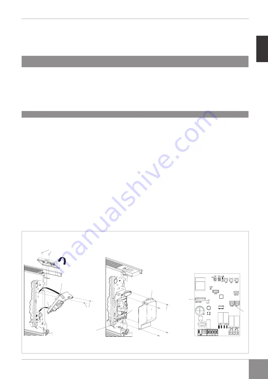
Slide the control panel into its housing in the upper part
of the device and fix it with the two fixing screws (ref. A).
To install the connection box:
-
open the box (ref. B);
-
lock the lower tooth into its hole (ref. C) on the side of
the device;
-
hook the upper part of the box to the side (ref. D);
-
fix it with the two fixing screws (ref. E);
-
connect the grounding cable to the fan coil body (ref. M)
using the fixing screws (the minimum force that must be
applied for tightening screws must be around 2N);
-
connect the fast connector of the MOTOR to the other
on the board (ref. I) *;
-
on the two GRID block terminals (ref. L) there is a bridge
that allows SLI and RSI versions to work without a
microswitch.
-
For other versions, remove the bridge and connect the
two terminals originating on the grill safety microswitch*;
-
connect the water probe to the H2 connector on the
device.
The water temperature probe controls the temperature
inside the batteries and determines when the fan starts
according to pre-set parameters (minimum operation
in winder and maximum in summer).** Check that
they are correctly inserted into the compartment on
the battery.
-
Connect the electrics, tidy cables and fix them with
the three clevises supplied (ref. G);
-
close the box with the 4 screws (ref. H);
-
refit the vanity plate on the side of the unit;
-
tighten the upper screws on the control panel;
-
place the screw head covers in their housing on the
control panel;
*
For versions with hydraulic connections on the right,
refer to the relevant paragraph
** The regulation also works without a water probe
connected
EN


