background image

CAEN


Electronic


Instrumentation


DT54xx


USB


High


Voltage


Power


Supply


5


1.


General


description


Overview


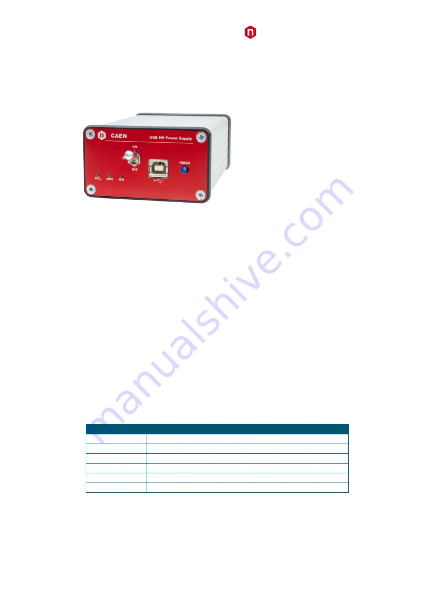
Fig.


1:


DT54xx


USB


High


Voltage


Power


Supply


The


DT54xx


series


modules


house


one


High


Voltage


Power


Supply


Channel


(1


W


max),


available


with


either


positive


or


negative


output


polarity.


The


units


are


supplied


and


controlled


via


USB


link;


HV


output


is


delivered


through


SHV


connector.


The


HV


output


RAMP

UP


and


RAMP

DOWN


rates


may


be


selected


independently


for


each


channel


with


1


V/s


steps.


Safety


features


include:


OVERVOLTAGE


and


UNDERVOLTAGE


warning


when


the


output


voltage


differs


from


the


programmed


value


(±2%)


Programmable


VMAX


hardware


protection


limit


OVERCURRENT


detection:


if


a


channel


tries


to


draw


a


current


larger


than


its


programmed


limit,


it


is


signalled


to


be


in


"overcurrent"


and


works


as


a


current


generator;


output


voltage


varies


in


order


to


keep


the


output


current


lower


than


the


programmed


value.


"Overcurrent"


lasting


more


than


set


value


(1


to


999


seconds)


causes


the


channel


to


"trip".


Output


voltage


will


drop


to


zero


either


at


the


Ramp

down


rate


or


at


the


fastest


available


rate,


depending


on


Power


Down


setting;


in


both


cases


the


channel


is


put


in


the


off


state.


If


trip=


INFINITE,


"overcurrent"


lasts


until


the


unit


is


switched


off


manually.


Output


can


be


enabled


or


disabled


through


the


Interlock


logic


and


the


relevant


switch.


The


following


versions


are


available:


Table


1:


Available


versions


Code


Model


WDT5470XNAAA

DT5470N

 ‐ 

USB


High


Voltage


Power


Supply

 ‐

5kV/200uA


(1W


max)

WDT5470XPAAA


DT5470P

 ‐ 

USB


High


Voltage


Power


Supply


+5kV/200uA


(1W


max)

WDT5471XNAAA

DT5471N

 ‐ 

USB


High


Voltage


Power


Supply

 ‐

3kV/500uA


(1W


max)

WDT5471XPAAA


DT5471P

 ‐ 

USB


High


Voltage


Power


Supply


+3kV/500uA


(1W


max)

WDT5472XNAAA

DT5472N

 ‐ 

USB


High


Voltage


Power


Supply

 ‐

500V/1mA


(0.5W


max)

WDT5472XPAAA


DT5472P

 ‐ 

USB


High


Voltage


Power


Supply


+500V/1mA


(0.5W


max)

A


software


Graphical


User


Interface


is


available


in


order


to


program


and


monitor


all


functional


parameters


of


the


modules


via


USB.


For


more


info


please


visit


www.caen.it


(products>firmware/software


section).


Summary of Contents for DT54 Series

Page 1: ...CAEN Tools for Discovery Electronic Instrumentation Es DT54xx USB High Voltage Power Supply Rev 4 19 January 2015...

Page 2: ...d has not been caused by mishandling negligence on behalf of the User accident or any abnormal conditions or operations CAEN declines all responsibility for damages or injuries caused by an improper u...

Page 3: ...vi 17 CAEN DT54XX lvlib Read out RAMP UP vi 18 CAEN DT54XX lvlib Debug Command vi 19 CAEN DT54XX lvlib Module Info vi 20 CAEN DT54XX lvlib Read out VMON vi 21 CAEN DT54XX lvlib Initialize vi 22 CAEN D...

Page 4: ...cal Connector 8 Fig 8 LC Optical Connector 8 Fig 9 Channel enable 8 Fig 10 HVmax trimmer 8 Fig 11 Main Menu 11 Fig 12 Channels Menu 11 Fig 13 Firmware Upgrade Menu 12 Fig 14 Format EEPROM Menu 12 Fig...

Page 5: ...urrent lasting more than set value 1 to 999 seconds causes the channel to trip Output voltage will drop to zero either at the Ramp down rate or at the fastest available rate depending on Power Down se...

Page 6: ...e Power Supply 6 2 Technical specifications Packaging and Compliancy The unit is a Desktop module housed in a 12 7x81x43 mm3 alloy box Power requirements The module is powered by the host PC USB link...

Page 7: ...and for safety reasons always connect to Earth the unit through this terminal before connecting HV Output to the load Interlock section Fig 5 Interlock connector AMP 280371 2 connector RED LED Input...

Page 8: ...tting USB Port Fig 7 USB Optical Connector B TYPE USB port USB2 0 compliant 200cm max cable length Status LEDs Fig 8 LC Optical Connector ON GREEN LED lights up when the channel is active OVC RED LED...

Page 9: ...output current lower than the programmed value Overcurrent lasting more than set value 0 to 999 causes the channel to trip Output voltage will drop to zero either at the Ramp down rate or at the fast...

Page 10: ...x to the PC via the USB cable Download and install the USB driver for your OS available at the DT54xx page on the www caen it site Now the DT54xx is ready for operation upon installation of one of the...

Page 11: ...CAEN and then Enter as the communication is established the Main Menu will be displayed Fig 11 Main Menu Type D to set monitor channel parameters Type F to format the EEPROM Type U to upgrade the firm...

Page 12: ...ig 13 Firmware Upgrade Menu If y is typed then the Flash is erased At this point it is necessary to upload the updated firmware If HyperTerminal is used it is necessary to perform Transfer and Send Te...

Page 13: ...050 510 210 ISRES A 0 2 0 1 0 04 IMRESH A 0 2 0 1 0 04 IMAXL A 105 51 21 IMRESL A 0 02 0 01 0 004 Command Format string CMD PAR VAL xxx xx CR LF CMD SET MON PAR VSET ISET ON VAL value Format of respon...

Page 14: ...ut Vmax hardware value Vmax can be set via hardware CMD MON PAR IMAX CR LF Read out ISET maximum value CMD MON PAR STAT CR LF Read out Status word Bit 0 ON 1 ON 0 OFF Bit 1 RUP 1 Channel Ramping UP Bi...

Page 15: ...xxx CR LF Set RDW RAMP DOWN value CMD SET PAR TRIP VAL xxx xx CR LF Set TRIP value CMD SET PAR PDWN VAL RAMP KILL CR LF Set power down mode RAMP or KILL CMD SET PAR IMRANGE VAL HIGH LOW CR LF Set ran...

Page 16: ...In order to install the DT54XX LabVIEW Instrument Driver Go to CAEN web site in the Software area of DT54xx HV Power Supply page Download the DT54XX LabVIEW Instrument Driver installation package Extr...

Page 17: ...or more information about the error VISA resource name BoardHandle is a reference to an open board error out error out passes error or warning information out of a VI to be used by other VIs Right cli...

Page 18: ...click the error out control on the front panel and select Explain Error or Explain Warning from the shortcut menu for more information about the error status status is TRUE X if an error occurred or F...

Page 19: ...he front panel and select Explain Error or Explain Warning from the shortcut menu for more information about the error source source describes the origin of the error or warning Right click the error...

Page 20: ...the response Response Response received from board Command Command sent to board CAEN DT54XX lvlib Module Info vi This function returns some information of the board Connector Pane Controls and Indica...

Page 21: ...ontrol on the front panel and select Explain Error or Explain Warning from the shortcut menu for more information about the error status status is TRUE X if an error occurred or FALSE checkmark to ind...

Page 22: ...front panel and select Explain Error or Explain Warning from the shortcut menu for more information about the error source source describes the origin of the error or warning Right click the error in...

Page 23: ...status is TRUE X if an error occurred or FALSE checkmark to indicate a warning or that no error occurred Right click the error in control on the front panel and select Explain Error or Explain Warning...

Page 24: ...cribes the origin of the error or warning Right click the error in control on the front panel and select Explain Error or Explain Warning from the shortcut menu for more information about the error VI...

Page 25: ...cut menu for more information about the error VISA resource name BoardHandle is a reference to an open board get more If get more is TRUE get more constant information releated a this parameter and re...

Page 26: ...ference to an open board error out error out passes error or warning information out of a VI to be used by other VIs Right click the error out control on the front panel and select Explain Error or Ex...

Page 27: ...rror status status is TRUE X if an error occurred or FALSE checkmark to indicate a warning or that no error occurred Right click the error out control on the front panel and select Explain Error or Ex...

Page 28: ...panel and select Explain Error or Explain Warning from the shortcut menu for more information about the error code code is the error or warning code Right click the error out control on the front pane...

Page 29: ...s is TRUE X if an error occurred or FALSE checkmark to indicate a warning or that no error occurred Right click the error in control on the front panel and select Explain Error or Explain Warning from...

Page 30: ...lain Warning from the shortcut menu for more information about the error source source describes the origin of the error or warning Right click the error in control on the front panel and select Expla...

Page 31: ...ormation about the error VISA resource name BoardHandle is a reference to an open board error out error out passes error or warning information out of a VI to be used by other VIs Right click the erro...

Page 32: ...de code is the error or warning code Right click the error in control on the front panel and select Explain Error or Explain Warning from the shortcut menu for more information about the error source...

Page 33: ...trol on the front panel and select Explain Error or Explain Warning from the shortcut menu for more information about the error error out error out passes error or warning information out of a VI to b...

Page 34: ...code Right click the error out indicator on the front panel and select Explain Error or Explain Warning from the shortcut menu for more information about the error source source string describes the...

Page 35: ...o indicate a warning or that no error occurred Right click the error in control on the front panel and select Explain Error or Explain Warning from the shortcut menu for more information about the err...

Page 36: ...is a reference to an open board error out error out passes error or warning information out of a VI to be used by other VIs Right click the error out control on the front panel and select Explain Err...

Page 37: ...out passes error or warning information out of a VI to be used by other VIs Right click the error out control on the front panel and select Explain Error or Explain Warning from the shortcut menu for...

Page 38: ...rder to install the DT54xx LabView Control Software Go to CAEN web site in the DT54xx page Download DT54xx Control Software package Unzip the package and launch the set up executable file Follow the i...

Page 39: ...Enable to do this Fig 18 Power Enable Box The Monitored values are reported by the relevant fields Fig 19 Monitor Fields The Channel Status box reports the actions that are going on Fig 20 Channel Sta...

Page 40: ...rol Software is running a datalog txt file is created in the sub folder CAEN_DT54XX_ControlSoftware of the default User s destination folder datalog txt records all the changes of the parameters runni...

Page 41: ...ers including engineers scientists and technical professionals who all trust them to help achieve their goals faster and more effectively CAEN S p A CAEN GmbH CAEN Technologies Inc Via Vetraia 11 Ecke...

Reviews: