Cadac CDC five_02-01-2020_Rev-7.docx
Page. 1 / 78
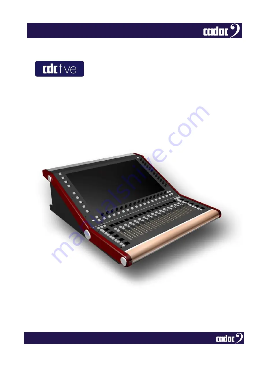
Cadac Digital Live Sound Mixing Console
Hardware Overview
Page 1: ...Cadac CDC five_02 01 2020_Rev 7 docx Page 1 78 Cadac Digital Live Sound Mixing Console Hardware Overview...
Page 2: ...Cadac CDC five_02 01 2020_Rev 7 docx Page 2 78...
Page 3: ...1 Console System Overview 13 Waves 14 MegaCOMMS Data Protocol 16 Console Features 17 Console Hardware Overview Surface 19 Control Surface Part 1 19 Control Surface Part 2 26 Console Hardware Overview...
Page 4: ...49 GO TO or Layers 50 Channel Meters 53 Channel Blocks 55 Using the Encoders 56 BUS Sends 58 Keyboard 59 User Layers 60 Effects 61 GEQ 63 Control Screen Menus 65 System Functions 70 Waves SoundGrid I...
Page 5: ...ersonnel Servicing is required when the apparatus has been damaged in any way such as the power supply cord or plug is damaged liquid has been spilled or objects have fallen into the apparatus the app...
Page 6: ...erence Follow all warnings in this manual and those printed on the console The console must be connected following the guidance in this manual Never connect power amplifier outputs directly to the con...
Page 7: ...armonised standards and technical specifications have been applied Electrical Safety LVD EN60950 1 2006 A2 2013 Electromagnetic Compatibility EN55032 2015 EN55013 2013 A1 2016 EN61000 3 2 2019 EN61000...
Page 8: ...ed user interface It makes most of the features developed over a 50 year period of innovation within large scale theatre and touring analogue desks and puts them within a compact fixed architecture di...
Page 9: ...upplies can also be specified Control Surface The control surface is divided in five operational areas 1 Graphical User Interface based around a 23 5 16 9 1920 x 1080 pixels touchscreen display with r...
Page 10: ...I O digital and AES3 2 Waves SoundGrid card 3 MegaCOMMS ports 4 MIDI Word Clock In Network and USB 5 PSU connectors For further detailed explanation of the control surface please see sections Console...
Page 11: ...I O including SRC CDC MC Dante 64 bidirectional channels of Dante I O including SRC CDC MC AES3 18 x AES3 inputs 18 x AES3 outputs 36 bidirectional audio channels CDC MC Optical up to 512 bi direction...
Page 12: ...provided by the CDC MegaCOMMS remote I O devices the control surface is provided with sixteen analogue mic line inputs eight analogue line outputs all balanced four balanced AES EBU inputs and four b...
Page 13: ...4 assignable mix busses plus left centre and right master busses and three monitor busses for PFL and AFL plus headphones The graphical interface on the 23 5 touchscreen screen has been designed to pr...
Page 14: ...e SoundGrid server processed and then streamed back to the console via Cat 5e The Waves processing is patched in the same way as the Cadac I O racks and can be used as a send and return for effects pr...
Page 15: ...record up to 64 tracks of 24 bit 96 kHz audio Example of a Waves Track Live integrated with a Cadac console For more information about using Waves Tracks Live please refer to the Waves website Etherne...
Page 16: ...embedding timing markers in the data stream This allows reliable low jitter synchronisation of all hardware elements within a network The simplest implementation of a MegaCOMMS network is the straigh...
Page 17: ...ays e g Mute group masters Input channels may be linked or paired for stereo operation 100 mm motorised faders with OLED displays of current assignments All output types groups auxes or matrices may b...
Page 18: ...hannel copy and isolate functions Full Monitor PFL and Talkback facilities 23 5 16 9 touchscreen display Scene automation with fast keypad access 96 kHz 24 bit Delta Sigma A D and D A converters Low n...
Page 19: ...Cadac CDC five_02 01 2020_Rev 7 docx Page 19 78 Console Hardware Overview Surface Control Surface Part 1 1 5 4 6 3 2 2 8 7 10 9 11 12 13 14 15...
Page 20: ...anual as vertical and horizontal The encoders also have press plus press and hold functions along with turn depending on the function used By default the lower set are the channel pan controls but may...
Page 21: ...g a Soft Mute a short press mutes the channel s output electronically at the fader any pre fade sends in use will remain active The ON button is not illuminated b Hard Mute a long press mutes the chan...
Page 22: ...signal present segment is green the five highest segments are red with the top one corresponding to 10 dBFS The remaining segments are yellow A METER Options page on the MENU screen allows the user t...
Page 23: ...OLED displays There are two sets or banks of 10 buttons selected by SET 1 and SET 2 default empty buttons at the top of the OLED display Other functions can be set for these buttons via the EDIT 14 b...
Page 24: ...a default allocation SET 2 are by default empty Allocation of a function to a button is done by selecting the function then the required SET and then the button within each SET or bank 3 User Define B...
Page 25: ...buttons accessing the screens and faders for the bus outputs The following buttons by default give access to LCR GO TO MONITORS DEFAULT MASTER PREVIOUS and NEXT CUE SET 2 are by default empty Other fu...
Page 26: ...Cadac CDC five_02 01 2020_Rev 7 docx Page 26 78 Control Surface Part 2 17 16 18 19 20 28 29 21 22 23 24 26 27 25 30 a 31...
Page 27: ...left right SCROLL 26 27 buttons allow navigation both up and down the busses While FADER FOLLOW Outputs is active the screen display and rotary encoders continue to be active for input channels The F...
Page 28: ...nto GEQ mode They will remain in this state until deselected 7 GEQ and MONITOR FOLLOW Bus sends VCAs can also be accessed via this page The members of each bus VCA remain the same as the normal VCA gr...
Page 29: ...liser function for that bus A 32 band graphic equaliser may be inserted in any or all output channels in addition to the channel s standard parametric EQ When GEQ is in use the OLEDs 11 display the ce...
Page 30: ...which is configured through setup options on the MENU screen Any of the local rear panel I O may be assigned as a Talkback output or a Return Talkback input 20 SOLO CLEAR Used to clear SOLO selection...
Page 31: ...in the STATUS bar will also allow access to the MENU screen The STATUS bar also displays the PROJECT name SHOW name the CUE as well as the TIME and the Rack configuration 24 MUTE ALL Pressing this bu...
Page 32: ...splays feature a virtual QWERTY keyboard but a hardware keyboard may be plugged in and used if preferred 29 SHIFT Enables the SCROLL RIGHT and SCROLL LEFT buttons to scroll by one rather than default...
Page 33: ...r supply 2 Backup PSU A12 pin Jaeger connector for a backup power supply a PSU 4800 sold separately 3 USB A type A USB 2 0 ports 4 Network RJ45 Ethernet ports for the connection of peripheral Ethernet...
Page 34: ...s always available at this connector at TTL level 0 to 5 V 9 MegaCOMMS 4 x BNC connectors in 2 pairs carrying all audio and control data between the control surface and other MegaCOMMS devices such as...
Page 35: ...8 V phantom power is enabled at the associated input connector 13 Outputs Eight balanced local analogue audio outputs from the CDC five on XLR male connectors Any output channel insert send or direct...
Page 36: ...X B OUT TX B 14 CDC five 2 pairs of MegaCOMMS ports The current stage boxes CDC I O 3216 and CDC I O 6448 have either two 1 pair or four 2 pairs BNC sockets The two paths A and B carry identical and s...
Page 37: ...be connected Set to 1 when connecting the stagebox to a CDC MC Router Set to 2 when connecting the stagebox to a console surface and it is to be used as RACK 1 Set to 3 when connecting the stagebox t...
Page 38: ...AES3 outputs have Sample Rate Converters SRCs and can operate at any frequency required by applying an external clock source to the WORD CLOCK IN connector The external clock must be selected on the...
Page 39: ...obstruct Rear Panel 5 Mains Input Neutrik powerCON TRUE1 male connector for AC mains Max rating 16 A A female powerCON connector is also provided this is paralleled to the input connector It may be us...
Page 40: ...fitted on the rear panel The CDC I O 6448 stagebox has a total of 64 inputs and 48 outputs while the CDC I O 3216 stagebox has 32 inputs and 16 outputs The CDC five can support one or two stageboxes...
Page 41: ...ystem input or output of any type channel input aux send channel insert matrix output etc anywhere in the console s architecture It should also be noted that the overall I O physical connectivity prov...
Page 42: ...maximum input level is 40 dBu with pad enabled When an input connector is assigned as the input of a channel in Mic mode 48 V phantom power is available also switched from the channel s Input Gain pan...
Page 43: ...Signal cold antiphase AES3 digital inputs Four AES3 digital audio inputs are available at the rear of the control surface on 3 pin XLR female connectors The AES3 format carries two independent audio c...
Page 44: ...acteristic impedance of 110 ohms Connections to these outputs should always be made using cable specifically designed for digital audio The digital outputs are equipped with Sample Rate Converters SRC...
Page 45: ...front armrest along with a volume attenuator for the headphones The socket is wired as follows Pin Connection Tip Left monitor output Ring Right monitor output Sleeve Screen common Waves SoundGrid in...
Page 46: ...n and reinstate the console to the last known settings Pressing YES also ignores all SAFES to allow the console to start in its previous state Touching CANCEL will result in the console operating in i...
Page 47: ...e shuts down a snapshot is taken of the current console status this includes all input and output channel settings 23 Power OFF screen Alternatively the surface can be powered down via the MENU screen...
Page 48: ...ay shows sixteen consecutive virtual channel strips and includes the most important information about the channels configuration and parameters More detailed information and access to controls for any...
Page 49: ...ve all the mapping to the encoders for that function It is possible to have more than one function open on the screen as some functions will map to the vertical encoders and others to the horizontal b...
Page 50: ...GN buttons The first three USER ASSIGN buttons to the right of the fader tray are by default set to GO TO Channel 1 17 and 33 The GO TO Bus 1 and 14 accessing the screens and faders to the bus outputs...
Page 51: ...action horizontally across the screen will shift the displayed set of channels by a number of channels proportional to the length of the swipe This is a very powerful feature of the CDC five and allo...
Page 52: ...ing SHIFT 29 this scroll can be reduced to one channel at a time NOTE Swiping or using the SCROLL buttons to go beyond INPUT channel 48 will display the main MIX BUSSES followed by the 24 OUTPUT chann...
Page 53: ...t levels The bar graphs have 20 segments the lowest segment illuminates green at a signal level of 80 dBFS and the top segment illuminates red at 10 dBFS indicating digital clipping The four segments...
Page 54: ...virtual bar graph dual on stereo channels complete with a 0 dB reference point The source for these may also be selected as PRE FADER or POST FADER on the METER OPTIONS page as described above so the...
Page 55: ...the relevant controls Channel Blocks Touching a channel block opens a virtual panel with all controls relevant to the block Mic Pre Compressor EQ Bus Routing Pan Virtual Meters Channel Description To...
Page 56: ...sing and holding the encoder it will zero any trim or return values back to the default position 33 DYNAMICS The DYNAMICS GUI has the functions mapped to the bottom 16 encoders Some functions for exam...
Page 57: ...is now on the vertical and the functions are now mapped to the 12 vertical encoders on the right The EQ GUI can also be scrolled up or down by touching and dragging the blank areas found in between th...
Page 58: ...route an INPUT DIRECT to a MATRIX output as well as routing the same INPUT to GROUP then ROUTING the GROUP to the MASTER L R and then route the MASTER L R to the same MATRIX The result would still be...
Page 59: ...nce in the SETTINGS screen select the INPUT OUPUT VCA etc for renaming and then press RENAME and this will bring up the virtual QWERTY keyboard on the screen 38 QWERTY keyboard An external USB keyboar...
Page 60: ...er of the channels can be navigated as normal unless all 16 channels are used 39 CUSTOM LAYERS Inputs with 2 x VCAs and 2 x Busses pinned to the screen USER LAYERS can be accessed through the MENU scr...
Page 61: ...d in any order using a simple drag and drop method Effects can be patched as inserts on any channel or bus or in line on an aux send return basis All the controls will map themselves to the relevant h...
Page 62: ...o mono allowing the Left and Right to be used as separate units 42 FX build screen select the element a choice of reverb delay and modulation and drag and drop into it one of the possible 9 slots A Wa...
Page 63: ...shown both on the screen and the OLEDs above the faders Pressing the SELECT button under the BUS will activate the GEQ for that individual BUS Once a fader is moved the ON light will illuminate blue...
Page 64: ...All parametric and graphic EQ s can be used simultaneously without any concern about available processing power or tonality compromise Additional features include GEQ in out an instant flat switch pl...
Page 65: ...ressing the CUE 21 button will bring up the CUE list 44 MENU SCREEN displaying the CUE list 45 MENU SCREEN displaying the CUE options displayed by double taping a CUE or pressing the STORE button The...
Page 66: ...DC five s automation system it enables file creation and management functions and is used when starting a new project or loading a previously stored one 46 MENU SCREEN displaying the PROJECTS menu CUE...
Page 67: ...NGS page opens on the screen and is used to set up the basic bus structure of the console busses may be defined as GROUPS AUXILIARY SENDS or MATRIX SENDS as MONO or STEREO and named GLOBAL channel sen...
Page 68: ...of taking the I O Patching Channels Modes Channel Head Amp I O Patching Outputs Bus Modes Outputs Brightness VCA Fader and VCA Mutes globally out of the automation SETTINGS menu provides access to opt...
Page 69: ...ched to the console This should be always be an external port REMOTE allows an iPad to control the console or accept any iPad controlling the console NOTE The BRIDGE SERVER must on start up be set to...
Page 70: ...aves license and playback 51 Waves SoundGrid Interface A range of optional Waves servers are also available from Waves which can be used to host the full range of Waves plug in signal processing See t...
Page 71: ...57 Waves 57 58 Waves 58 59 Waves 59 60 Waves 60 61 Waves 61 62 Waves 62 63 Waves 63 64 Waves 64 Output Waves Local IO 1 Waves 1 2 Waves 2 3 Waves 3 4 Waves 4 5 Waves 5 6 Waves 6 7 Waves 7 8 Waves 8 9...
Page 72: ...nection of a standard USB QWERTY keyboard and or mouse Ethernet Ports The CDC five is equipped with 2 RJ45 Ethernet Ports These are standard PC network Gigabit Ethernet ports for purposes of connectin...
Page 73: ...four USB ports on the console and then follow the on screen instructions CDC five Console Software Upgrade Procedure 1 Important Backup all show files that are on the console 2 Download the Console S...
Page 74: ...hannels 48 with full processing Busses 24 configurable in pairs as group aux st aux plus dedicated LCR monitor LR headphones LR and talkback Matrix Up to 67 x 48 with full processing Outputs Up to 192...
Page 75: ...hrough complete signal chain Internal Processing 40 bit floating point ADC DAC 24 bit Frequency Response 20 Hz to 44 kHz 0 5 1 5 dB THD N better than 0 005 unity gain 10 dB input at 1 kHz Channel Sepa...
Page 76: ...Cadac CDC five_02 01 2020_Rev 7 docx Page 76 78 Dimensions Weight 37kgs 81 57lbs approx...
Page 77: ...Cadac CDC five_02 01 2020_Rev 7 docx Page 77 78...
Page 78: ...served under International and Pan American Copyright Conventions All trademarks are the property of their respective owners No part of this publication may be reproduced in any form or by any means w...