Micro-CS Overview
Micro-CS Installation Guide
1-7
1.5.7
Modem Status LEDs
The modem LEDs provide information on modem activity
1.5.8
SETUP Switch
The SETUP button allows you to change the operational mode of the
Micro-CS from Normal to Test. It also functions as a Reset button (see
Note below). The Micro-CS automatically powers up in normal mode. To
enter test mode, press the SETUP button within three seconds of
powering-up.
Additionally, a Setup signal is provided from the MicroMMAC
motherboard. When this signal is active, it will perform a cold start of the
Micro-CS.
1.5.9
Port Activity Indicators
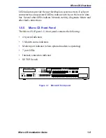
The LED activity indicators associated with ports 1-7 blink to indicate
data either data transmitted to or received by that port. The “M” port
lights to indicate the modem is seeing activity. The 5 modem LED’s blink
to indicate the modem is sending or receiving data from the WAN
network.
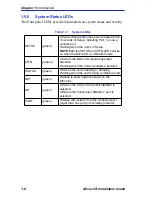
Table 1-2
: Modem LEDs
TxD
(green)
Flashes to indicate modem has transmitted
data to remote modem via dial up link.
RxD
(green)
Flashes to indicate data received from
remote modem over dial up link.
DTR
(green)
On when optional modem receives Data
Terminal Ready from the Micro-CS.
CTS
(green)
On until the modem lowers Clear To Send
when transmit Data hardware flow control is
enabled. Always on during synchronous
connections.
DCD
(green)
On when optional modem receives a valid
Data Carrier Detect signal from a remote
modem, indicating that data transmission is
possible.
Summary of Contents for MicroMMAC 22ES
Page 2: ......
Page 8: ...vi Micro CS Installation Guide...
Page 12: ...Contents iv Micro CS Installation Guide...
Page 22: ...Chapter 1 Introduction 1 10 Micro CS Installation Guide...
Page 32: ...Chapter 2 Micro CS Installation 2 10 Micro CS Installation Guide...
Page 72: ...Chapter 4 Troubleshooting Procedures 4 14 Micro CS Installation Guide...
Page 82: ...Appendix C Flash Upgrade Instructions C 4 Micro CS Installation Guide...


