
INSTRUCTION, USE AND
MAINTENANCE MANUAL
GB
Page 24 of 68
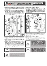
• Move to work position
B
(
Fig. 11
).
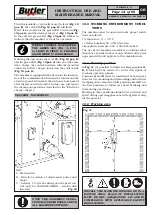
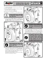
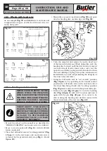
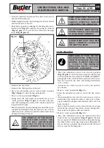
• Lower the mandrel completely. Roll the tyre next to
the mandrel and hook it to clamp (
Fig. 28 pos. 1
).
• Lift the mandrel with the tyre hooked and turn it
clockwise by about 15-20 cm; the tyre will position
itself sideways with respect to the rim (see
Fig. 28
).
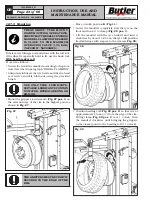
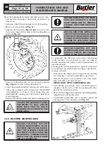
• Place the roll holder arm in “off-work” position (
Fig.
18 pos. 1
); translate it to the inner side of the tyre
and hook it again into “work position” (
Fig. 17 pos.
1
).
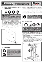
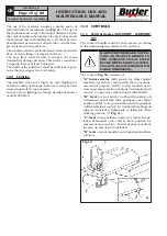
• Mount the hook tool on the roll, by positioning it on
the side of the tyre (see
Fig. 30
).
Fig. 30
• Move to work position
C
(
Fig. 11
).
• Move the tool forward until the reference notch
matches the external edge of the rim coincide at about
5 mm from the rim itself.
• Move to work position
B
(
Fig. 11
).
• From the external side of the wheel, check the exact
position of the tool and, if necessary, correct it. Then,
turn the mandrel clockwise until the grippers reach
in the closest point to the tool (11 o’clock). The first
bead should now be inserted in the rim.
• Remove the grippers.
• Move to work position
C
(
Fig. 11
).
• Extract the tool from the tyre.
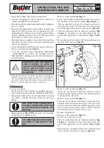
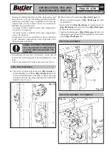
• Place the roll holder arm in “off-work” position (
Fig.
18 pos. 1
); translate it to the outer side of the tyre
and hook it again into “work position” (
Fig. 17 pos.
1
).
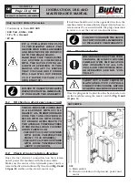
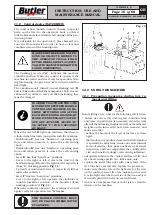
• Remount the tool holder head at 180° until the hook
tool is moved onto the tyre side (see
Fig. 24
).
7503-M002-6_B
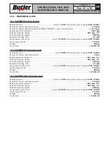
NAV26HW - NAV26HW.S - NAV26HW.ST
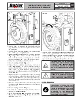
• Move the beading roll away from the wheel.
• Remove the grippers and fit them in position (6
o’clock) outside the second bead.
• Turn the mandrel counterclockwise until the grippers
are at 1 o’clock.
• Move the beading roll forward until it is inside the
edge of the rim by about 1-2 cm, making sure it is
approximately 5 mm from the rim. Begin clockwise
rotation making sure that, after a 90° turn, the second
bead begins to slide in the rim groove.
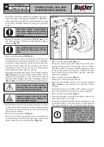
• Once insertion is completed, move the roll away from
the wheel, turn it over into “out of work” position and
remove the grippers.
• Lower the mandrel until the wheel rests on the floor.
• Move to work position
A
(
Fig. 11
).
• Close the mandrel jaws completely (NAV26HW
- NAV26HW.S) or remove the locking ring nut
(NAV26HW.ST) making sure the wheel is held up to
avoid dropping.
MAKE SURE THAT THE WHEEL’S
HOLD IS SECURE TO AVOID IT
FALLING DURING REMOVAL. FOR
HEAVY AND/OR VERY LARGE
WHEELS USE AN ADEQUATE LIFT-
ING DEVICE.
• Remove the wheel from the machine by making it
roll. By using particularly soft tyres, it is possible to
put on the rim both the beads at the same time, in
order to operate only one time on the tyre.
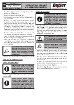
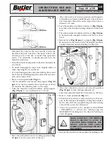
With hook tool
Proceed as follows:
• Secure the rim to the mandrel according to the proce-
dure described in paragraph “WHEEL CLAMPING”.
• Adequately lubricate the tyre beads and the rim bead
seat with a suitable lubricant using the provided
brush.
USE ONLY TYRE LUBRICANTS.
SUITABLE LUBRICANTS CONTAIN
NO WATER, HYDROCARBONS, OR
SILICON.
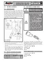
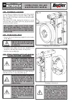
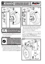
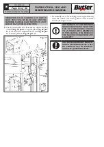
• Mount grippers (
Fig. 27 Pos. 1
) on the external edge
of the rim in the highest point.
.
THE GRIPPERS MUST BE TIGHTLY
SECURED TO THE EDGE OF THE
RIM.


