
INSTRUCTION, USE AND
MAINTENANCE MANUAL
GB
Page 20 of 68
A.
Lock the wheel on the mandrel as described in the
previous paragraph.
B.
Remove all balancing weights from the rim. Extract
the valve and let air out of tyre.
C.
Move to work position
A
(
Fig. 11
).
D.
Position the beading disc on the external side of
the tyre.
ALWAYS VERIFY THAT THE ARM
IS CORRECTLY LOCKED TO THE
SHIFTING BEAM.
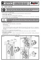
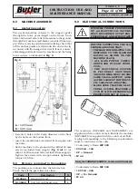
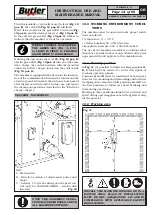
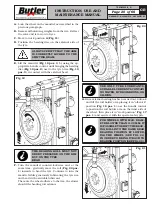
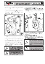
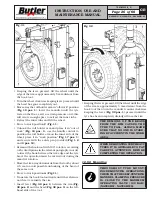
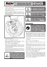
E.
Lift the mandrel (
Fig. 19 pos. 1
) by using the ap-
propriate handle control, until bringing the beading
disc (
Fig. 19 pos. 2
) next to the tyre brim (
Fig. 19
pos. 3
), in contact with the external bead.
Fig. 19
THE BEADING ROLL MUST NOT
EXERT PRESSURE ON THE RIM
BUT ON THE TYRE
BEAD
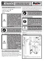
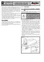
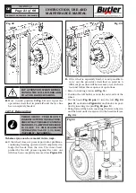
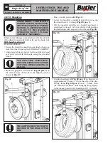
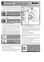
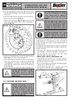
F.
Turn the mandrel counterclockwise and, at the
same time, gradually move the roll (
Fig. 20 pos.
1
) inwards to bead the tyre. Continue to turn the
mandrel while generously lubricating the tyre rim
and bead with a suitable lubricant.
The more the wheel adheres to the rim, the slower
should the beading roll advance.
Fig. 20
USE ONLY TYRE LUBRICANTS.
SUITABLE LUBRICANTS CONTAIN
NO WATER, HYDROCARBONS, OR
SILICON.
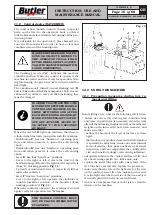
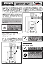
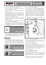
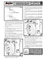
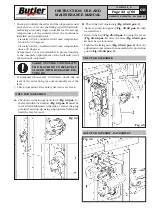
G.
Once external beading has been carried out, unhook
and lift the roll holder arm placing it in “off-work”
position (
Fig. 18 pos. 1
); use the handle control
to position the roll holder arm on the inner side of
the wheel, then place it in “work position” (
Fig. 17
pos. 1
) and secure it with the special safety pin.
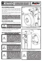
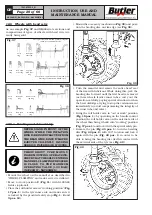
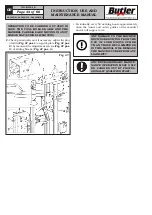
FOR WHEELS WITH MAX. DIAM-
ETER LOWER THAN 1100 MM, IT
IS POSSIBLE TO SHIFT THE BEAD-
ING ROLL INTO THE SAME REAR
BEADING POSITION BY LOWER-
ING THE WHEEL (SEE FIG. 21)
IN ORDER TO BRING IT BACK TO
BEADING POSITION (SEE FIG. 22).
Fig. 21
7503-M002-6_B
NAV26HW - NAV26HW.S - NAV26HW.ST


