background image

Product Description

Use

The vacuum pump is intended for

the suction

of

air and other dry, non-aggressive, non-toxic and non-explosive
gases

Conveying media with a lower or higher density than air leads to an in-
creased thermal and/or mechanical load on the vacuum pump and is
permissible only after prior consultation with Busch.

Permissible temperature range of the inlet gas: see “Oil”, “Ambient
temperature range”

In case the vacuum pump is equipped with a gas ballast (optional) wa-
ter vapour within the gas flow can be tolerated within certain limits
(

Ú

page 8: Conveying Condensable Vapours). The conveyance of

other vapours shall be agreed upon with Busch.

The vacuum pump is intended for the placement in a non-potentially
explosive environment.

Version with oil return line to the B-cover (RA ... C, 2 mbar):

Version with oil return line to the suction connection (RC ... C):

The vacuum pump is thermally suitable for continuous operation
(100 percent duty).

Version with oil return valve (RA ... C, 0.5 mbar):

The vacuum pump is thermally suitable for continuous operation (ob-
serve the notes with regard to the oil recirculation:

Ú

page 3: Oil Cir-

culation;

Ú

page 8: Oil Return).

The vacuum pump is ultimate pressure proof.

Principle of Operation

The vacuum pump works on the rotating vane principle.

A circular rotor is positioned centrically on the shaft of the vacuum
pump. The shaft of the vacuum pump is driven by the drive motor
shaft by means of a flexible coupling.

The rotor rotates in an also circular, fixed cylinder, the centreline of
which is offset from the centreline of the rotor such that the rotor and
the inner wall of the cylinder almost touch along a line. Vanes, sliding
in slots in the rotor, separate the space between the rotor and the cyl-

i

nder into chambers. At any time gas is sucked in and at almost any

time ejected. Therefore the vacuum pump works almost pulsation free.

In order to avoid the suction of solids, the vacuum pump is equipped
with a screen  in the suction connection.

In order to avoid reverse rotation after switching off, the vacuum
pump is equipped with a non-return valve.

Note: This valve shall not be used as a non-return valve or shut-off
valve to the vacuum system and is no reliable means to prevent suction
of oil into the vacuum system while the vacuum pump is shut down.

In case the vacuum pump is equipped with a gas ballast (optional):

Through the gas ballast a small amount of ambient air is sucked into
the pump chamber and compressed together with the process gas.
This counteracts the accumulation of condensates from the process gas
inside the vacuum pump (

Ú

page 8: Conveying Condensable

Vapours).

The gas ballast line is equipped with a paper filter.

In order to improve the operating characteristics the outlet of the
pump chamber is equipped with a spring loaded valve.

Oil Circulation

The vacuum pump requires oil to seal the gaps, to lubricate the vanes
and to carry away compression heat.

The oil reservoir is located on the pressure side of the vacuum pump
(i.e. high pressure) at the bottom of the bottom chamber of the oil
separator (e).

The feed openings are located on the suction side of the vacuum pump
(i.e. low pressure).

Forced by the pressure difference between pressure side and suction
side oil is being drawn from the oil separator (e) through the oil supply
lines and injected on the suction side.

Together with the sucked gas the injected oil gets conveyed through
the vacuum pump and ejected into the oil separator (e) as oil mist. Oil
that separates before the exhaust filter accumulates at the bottom of
the bottom chamber of the oil separator (e).

Oil that is separated by the exhaust filter accumulates at the bottom of
the upper chamber of the oil separator (e).

The flow resistance of the exhaust filters causes the inside of the ex-
haust filters (which is connected to the bottom chamber of the oil sep-
arator) to be on a higher pressure level than the outside of the exhaust
filters (i.e. the upper chamber of the oil separator). Because of the

                                                                                           3

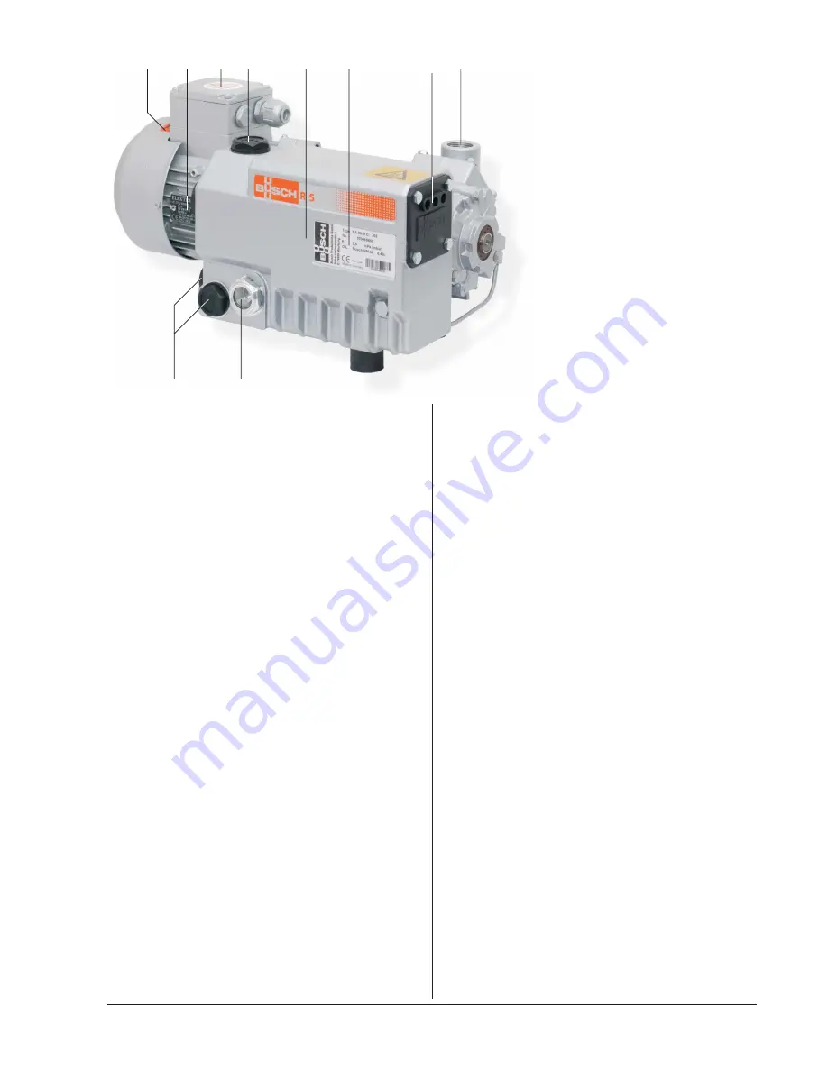
a            b          c        d                  e              f                            g        h

i                       j

a

Directional arrow

b

Nameplate, drive motor

c

Terminal box

d

Oil fill plug

e

Oil separator

f

Nameplate, vacuum pump

g

Gas discharge

h

Suction connection

i

Oil drain plug

j

Oil sight glass

Summary of Contents for R 5 RA/RC 0010 C

Page 1: ...Installation and Operating Instructions Rotary Vane Vacuum Pumps R 5 RA RC 0010 0016 C Busch LLC 516 Viking Drive Va Beach VA 23452 Phone 757 463 7800 Fax 757 463 7407 P N 0872 918 377 0909 ...

Page 2: ......

Page 3: ...shooting 13 Oil 18 EC Declaration of Conformity 19 Service Centers 20 Busch All over the World in Industry 21 2 Preface Congratulations on your purchase of the Busch vacuum pump With watchful observation of the field s requirements innovation and steady development Busch delivers modern vacuum and pressure solutions worldwide These operating instructions contain information for product description...

Page 4: ...id reverse rotation after switching off the vacuum pump is equipped with a non return valve Note This valve shall not be used as a non return valve or shut off valve to the vacuum system and is no reliable means to prevent suction of oil into the vacuum system while the vacuum pump is shut down In case the vacuum pump is equipped with a gas ballast optional Through the gas ballast a small amount o...

Page 5: ... the vacuum pump these installation and operating instructions shall be read and understood If anything remains to be clarified please contact your Busch representative Safety Notes The vacuum pump has been designed and manufactured according to state of the art methods Nevertheless residual risks may remain These operating instructions highlight potential hazards where appro priate Safety notes a...

Page 6: ...ack the surfaces of plastics and elastomers Seek advice from your local packaging dealer Busch uses CORTEC VCI 126 R film for the overseas packaging of large equipment Wrap the vacuum pump in VCI film Store the vacuum pump if possible in original packing indoors dry dust free and vibration free For commissioning after conservation Make sure that all remains of adhesive tape are removed from the po...

Page 7: ...condensates can be drained from the suction line Make sure that the suction line does not contain foreign objects e g welding scales CAUTION_a The discharged gas contains small quantities of vacuum oil Staying in vacuum oil contaminated air bears a risk of damage to health If air is discharged into rooms where persons stay sufficient ventila tion must be provided for Electrical Connection Controls...

Page 8: ... to be filled in CAUTION_a Filling oil through the suction connection h will result in breakage of the vanes and destruction of the vacuum pump Oil may be filled through the filling port d only CAUTION_a During operation the oil separator is filled with hot pressurised oil mist Risk of injury from hot oil mist with open filling port Risk of injury if a loosely inserted filling plug d is ejected Re...

Page 9: ...quired contact or heat protection gloves shall be worn CAUTION_a The gas conveyed by the vacuum pump contains remainders of oil Aspiration of process gas over extended periods can be harmful The room into which the process gas is discharged must be suffi ciently vented Make sure that all provided covers guards hoods etc remain mounted Make sure that protective devices will not be disabled Make sur...

Page 10: ...lle and the cooling fins Every Year Make sure that the vacuum pump is shut down and locked against inadvertent start up Replace the exhaust filter Ú page 10 Exhaust Filter In case an inlet air filter is installed Replace the inlet air filter Check the inlet screen clean if necessary Version with gas ballast with paper filter Replace the filter Every 500 2000 Operating Hours Ú page 10 Oil Life Chan...

Page 11: ...dvertent start up Remove the drain plug i again and drain the remaining oil Make sure that the seal ring is inserted into the drain plug i and undamaged replace if necessary Firmly reinsert the drain plug i together with the seal ring Dispose of the used oil in compliance with applicable regulations Flushing the Vacuum Pump WARNING_ad Degraded oil can choke pipes and coolers Risk of damage to the ...

Page 12: ...r retaining spring but do not remove it at this time Press the exhaust filter retaining spring out of the indent and rotate it Remove the exhaust filter retaining spring from the oil sepa rator e Pull the exhaust filter out of the oil separator e Inserting the Exhaust Filter CAUTION_a The non OEM spares market offers exhaust filters that are geomet rically compatible with Busch vacuum pumps but do...

Page 13: ...motor If deposits could have gathered in the vacuum pump Flush the vacuum pump Ú page 9 Maintenance Observe the chapter Installation and Commissioning Ú page 5 Dismantling and Disposal DANGER_age32 In case the vacuum pump conveyed gas that was contaminated with harmful foreign material the oil and the exhaust filter s will be contaminated with harmful material Harmful material can reside in pores ...

Page 14: ...oil the most common cause Change the oil Ú page 9 Maintenance No or not enough oil in the reservoir Top up oil Ú page 9 Maintenance The exhaust filter is partially clogged Replace the exhaust filter Ú page 9 Maintenance The screen in the suction connection h is partially clogged Clean the screen If cleaning is required too frequently install a filter upstream In case a filter is installed on the s...

Page 15: ...or is overloaded Supply the drive motor with the correct volt age The drive motor starter overload protection is too small or trip level is too low Compare the trip level of the drive motor starter overload protection with the data on the nameplate correct if necessary In case of high ambient temperature set the trip level of the drive motor starter overload protection 5 percent above the nominal ...

Page 16: ...ommission ing Loose connection s in the drive motor termi nal box Version with three phase motor Not all drive motor coils are properly con nected The drive motor operates on two phases only Check the proper connection of the wires against the connection diagram particularly on motors with six coils Tighten or replace loose connections Version with three phase motor The vacuum pump runs in the wro...

Page 17: ...ging of filters or screens Partial clogging in the suction discharge or pressure line Remove the clogging Long suction discharge or pressure line with too small diameter Use larger diameter The vacuum pump fumes or expels oil drop lets through the gas discharge The oil level drops The exhaust filter is not properly seated Check the proper position of the exhaust fil ter if necessary insert properl...

Page 18: ...oil life is too short use oil with better heat resistance Ú page 18 Oil or ret rofit cooling The oil is watery and coloured white The vacuum pump aspirated water or signifi cant amounts of humidity Version with gas ballast The filter of the gas ballast is clogged Flush the vacuum pump Replace the exhaust filter Fill in new oil Ú page 9 Maintenance Modify the operational mode Ú page 8 Op erating No...

Page 19: ...Oil l x o r p p a y t i t n a u q g n i l l i F 18 Recommended oil type Busch R 580 0 4 l x o r p p a y t i t n a u q g n i l l i F Alternative oil type 0 4 VM 068 VSL 068 ...

Page 20: ...ithin Certain Voltage Limits so called Low Voltage 2006 95 EC Electromagnetic Compatibility 2004 108 EC have been designed and manufactured to the following specifications Standard Title of the Standard Harmonised Standards EN ISO 12100 1 EN ISO 12100 2 Safety of machinery Basic concepts general principles of design Part 1 and 2 EN 294 Safety of machinery Safety distance to prevent danger zones be...

Page 21: ...t 420 E Street Suite 4 South Plainfield NJ 07080 Minillas Industrial Park Phone 908 561 3233 Bayamon PR 00959 1901 Fax 908 561 3909 Phone 787 798 5045 service nj buschusa com Fax 787 798 5033 service pr buschusa com Texas Virginia 1901 South Starpoint Drive 516 Viking Drive Houston TX 77032 Virginia Beach VA 23452 Phone 281 214 8400 Phone 757 463 7800 Fax 281 214 8410 Fax 757 463 7407 service tx b...

Page 22: ......

Page 23: ......

Page 24: ...owth Junction Business Centre Kilbarrack Dublin 5 Tel 00353 1 832 1466 Fax 00353 1 832 1470 Italy Busch Italia S r l Via Ettore Majorana 16 20054 Nova Milanese Tel 0362 370 91 Fax 0362 370 999 Japan Nippon Busch K K 1 23 33 Megumigaoka Hiratsuka City Kanagawa Japan 259 1220 Tel 0463 50 4000 Fax 0463 50 4004 Korea Busch Korea Ltd 392 1 Yangji Ri Yangji Myun Yongin si Kyunggi Do Tel 031 321 8114 Fax...

Reviews: