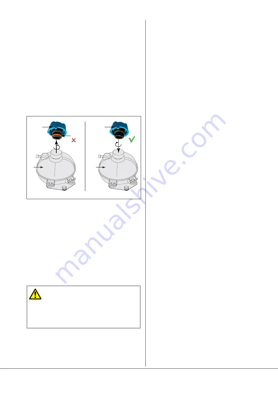
Filling in cooling liquid
The COBRA NC vacuum pumps are always delivered without cooling
liquid (see chapter “Cooling liquid types”, page
21
, for information
on the recommended cooling liquids).
l
Prepare the quantity of cooling liquid as specified in the table
“Cooling liquid quantity” (approx. 27 litres)
NOTE
: The quantity of cooling liquid specified in the installation
handbook is of informative nature only. Follow the procedure of filling
the cooling liquid.
l
Unscrew the cooling liquid filler plug (CLF) on the expansion vessel
(EV)
l
Remove the red o-ring (SR) of the cooling liquid filler plug (CLF)
l
Fill in cooling liquid. Make sure that the filling level is between the
MIN/ MAX marks of the expansion vessel (EV)
l
Stop the filling
l
Fit the cooling liquid filler plug (CLF) (without o-ring (SR)
l
Wipe any spillage off the expansion vessel (EV) and the vacuum
pump
l
Start the vacuum pump
If the inlet line is equipped with a shut-off device:
u
Close the shut-off device
If the inlet line is not equipped with a shut-off device:
u
Place a rubber mat on the suction flange
l
Let the vacuum pump run for maximum 5 minutes
l
Stop the vacuum pump and wait for a few minutes
l
Check that the filling level is always between the MIN/ MAX
marks of the expansion vessel (EV)
l
In case the cooling liquid level is below the required level:
u
Fill in more cooling liquid
CAUTION
The cooling circuit with water/water heat exchanger or air/water
heat exchanger, which is connected to the vacuum pump, must also
be completely vented.
In order to able to be vented, the connected cooling circuit must be
situated lower than the vacuum pump.
If the inlet line is equipped with a shut-off device:
u
Open the shut-off device
If the inlet line is not equipped with a shut-off device:
u
Remove the rubber mat from the suction flange and connect
the suction line to the suction flange
Connection of the barrier gas
The vacuum pump is equipped with a barrier gas system for the
labyrinth seals.
Connect compressed air with 3 to 10 bar to the barrier gas connection
(BGS) and with the overpressure valve (BGR), set the barrier gas
overpressure to 3 bar.
Shortly before starting the pump until shortly after stopping it, the
vacuum pump has to be continually pressurised with barrier gas.
Saving the operating parameters
As soon as the vacuum pump is working under normal conditions after
being switched on:
l
Measure the working current of the motor and the vibration
transmitter (SA) and keep them as reference values for all future
maintenance and repair work
Start-up
Vacuum pump
Before starting up the vacuum pump, the entire Installation and
Operating Instructions must be read and understood.
Before operation, the pump must imperatively be filled with the
relevant gear oil and cooling liquid and their levels must be checked;
top up if necessary.
In case of wrong direction of rotation of the pump, extensive damage
can occur. Press the Start/ Stop button only briefly to check the
direction of rotation with the help of the motor fan.
After start-up, the vacuum pump has to be checked every day for
any
unusual noise. In such a case, immediately stop the pump, see
paragraph “Troubleshooting”
Keeping to the temperature class
The temperature class of the vacuum pump is defined for the inside
(i)
zone, see the explosion protection group markings on the vacuum
pump and also this installation manual. The inside zone is in contact
with the drawn gases.
The temperature class is monitored by the temperature sensor TS.
The
maximum value for the temperature sensor is defined in the
chapter
“Installation and Commissioning”.
The monitored values depend on several operating values. In order to
ensure trouble-free operation, the initial adjustments must only be
carried out by specialised
Busch
s
taff during the initial start-up of the
pump.
The following operating values have a direct influence on the
monitored temperatures:
–
Entry temperature of the gases (60°C)
–
Differential pressure between the entry and outlet of the cooling
medium
–
Cooling medium temperature
–
Pressure on suction side and exhaust side
–
Operating frequency
–
Ambient temperature
If an operating value is modified at a later date thereby causing an
increase of the gas temperature, the adjustment of the thermostatic
valve must be adjusted accordingly.
Installation and Commissioning
Page 11
CLP
SR
EV
CLP
EV
Summary of Contents for 7180551
Page 24: ......
Page 26: ...Temperature sensor TS Temperature sensor TS Page 26...
Page 27: ...Temperature sensor TS Page 27...
Page 28: ...Temperature sensor TS Page 28...
Page 29: ...Temperature sensor TS Page 29...
Page 34: ...Note...
Page 35: ...Note...


