Discharge connection
CAUTION
Do not put hands into the outlet aperture.
Risk of body damage !
The following instructions for connection to the discharge side only
apply if the drawn gas is discharged into a suitable environment by the
vacuum pump.
l
Make sure that the protection that was fitted to prevent the
ingress of particles during transport has been removed before the
vacuum pump is connected up to the vacuum pipe
l
Make sure that the nominal diameter of the discharge line
corresponds at least to the diameter of the exhaust flange of the
vacuum pump in order to prevent a drop in the performance of the
vacuum pump, in case of use of a smaller cross-section
CAUTION
When the discharge piping has been connected up, make sure that
the system does not leak. Leakage of dangerous substances must be
prevented!
l
Make sure that the discharge line is fitted in such a way as to
prevent any liquids or condensates to re-enter the vacuum pump
(siphon, discharge line sloping away from the pump)
l
Make sure that the discharge line is not equipped with a shut-off
device
l
Make sure that the discharge line does not exercise any pressure
onto the exhaust flange. Use bellows if necessary
l
The outlet flange has the following dimension:
–
DN 80 PN6 or ISO-K DN 63
l
Maximal counter pressure at the discharge:
–
0,1 bar
In the case of long discharge lines, the line cross-section should be
larger than the exhaust flange in order to prevent a drop in the
performance of the vacuum pump. If you have any doubts, contact
your Busch representative.
Electrical connection/ Checks
The electrical installation must only be carried out by a specialist.
The regulations according to European Standard EN 50081 and EN
50082 (electromagnetic compatibility), EN 60079 Part 17 and 19, as
well as EN 60204 (machine safety, electrical equipment of machines)
and VDE 0100 (setting up of high voltage equipment with nominal
voltages up to 1000 V) must be observed.
The end user’s mains supply must comply with the regulations
according to European Standard EN 50081 and EN 50082
(electromagnetic compatibility). If this is not the case, the manufacturer
of the vacuum system must be notified.
If the motor’s direction of rotation is wrong, the pump can be seriously
damaged.
In order to change the direction of rotation, two phases on the motor
must be swapped around.
l
Make sure that the requirements according to EMC-Directive
2014/30/EU as well as the current EN-standards, electrical and
occupational safety directives and the local or national regulations
respectively, are complied with (this is the responsibility of the
designer of the machinery into which the vacuum pump is to be
incorporated; see also the corresponding comments in the
EU-Declaration of Conformity)
l
Make sure that the power supply is compatible with the data on
the nameplate of the drive motor
l
Make sure that an overload protection according to EN 60204-1 is
provided for the drive motor
l
Make sure that the drive of the vacuum pump will not be affected
by electric or electromagnetic interference; if unsure please seek
advice from your Busch representative
Cooling liquid level control
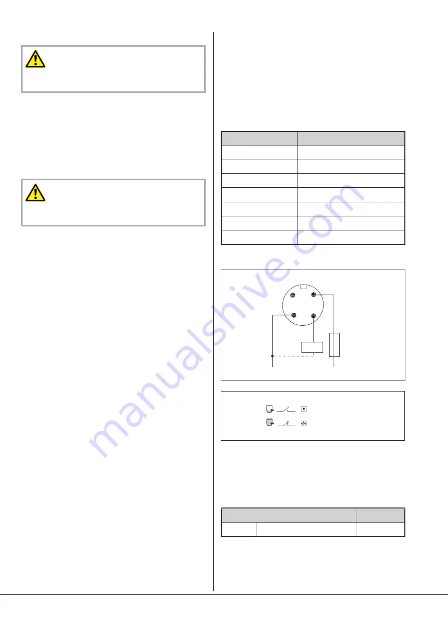
The cooling liquid level is supervised by a level switch LS that is
mounted in the inlet side cylinder cover.
The electrical connection of the level switch (LS) has to be done in such
a way that the vacuum pump stops when the level switch (LS) detects
a too low level of cooling liquid for moore than 30 seconds.
Technical data
Technical data
Level switch LS
Type
Liquiphant FTL31-AA4M3AAW5J
Breaking capacity
200 mA
Current consumption
< 15 mA
Power consumption
< 975 mW
Range
> 0,7 g/cm
3
Supply voltage
10...30 VDC
Connector
M12 x 1 Type Binder
Electrical wiring diagram
Cooling Liquid Temperature Monitoring
The cooling liquid temperature is monitored by a PT100 temperature
sensor (TS).
The PT100 temperature sensor (TS) must be electrically connected in
such a way that the vacuum pump stops if the cooling liquid
temperature exceeds 65°C.
Designation
Set value [°C]
TS
PT 100 Cooling liquid temperature
65
Installation and Commissioning
Page 8
1 : BN
2
3 : BU
4 : BK
0.5 A
L +
L -
K
1
4
1
4
LED not lit (red)
LED lit (yellow)
Summary of Contents for 7180551
Page 24: ......
Page 26: ...Temperature sensor TS Temperature sensor TS Page 26...
Page 27: ...Temperature sensor TS Page 27...
Page 28: ...Temperature sensor TS Page 28...
Page 29: ...Temperature sensor TS Page 29...
Page 34: ...Note...
Page 35: ...Note...


