


70
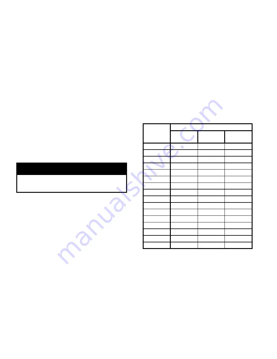
TABlE 1: GAS FlOW RATE IN CUBIC FEET
PER hOUR
O.
Check limit.
1. Adjust thermostat to highest setting.
2. Observe temperature gauge. When temperature is
indicated, adjust limit to setting below observed
temperature. Main burners and pilot burner should
extinguish, and blower should stop.
3. Adjust limit to setting above observed temperature.
Ignition sequence should begin.
4. Adjust thermostat to lowest setting. Adjust limit to
desired setting.
P.
Adjust gas input rate to boiler.
1. Adjust thermostat to highest setting.
2. Check manifold gas pressure. See Table 5 or rating
label located in the boiler’s vestibule compartment.
Adjust gas valve pressure regulator as necessary
(turn adjustment screw counterclockwise to
decrease manifold pressure, or clockwise to increase
manifold pressure). If pressure cannot be attained,
check gas valve inlet pressure. If less than minimum
indicated in Table 5 or boiler’s rating label, contact
gas supplier for assistance.
3. Clock gas meter for at least 30 seconds. Use Table
13 to determine gas flow rate in Cubic Feet per
Hour.
WARNING
Failure to properly adjust gas input rate will result
in over firing or under firing of the appliance.
Improper and unsafe boiler operation may result.
4. Determine Input Rate. Multiply gas flow rate by gas
heating value.
5. Compare measured input rate to input rate stated on
rating plate.
a. Boiler must not be over fired. Reduce input rate
by decreasing manifold pressure. Do not reduce
more than 0.3 inch w.c. If boiler is still overfired,
contact your Burnham distributor or Regional
Office for replacement Gas Orifice.
b. Increase input rate if less than 98% of rating
plate input. Increase manifold gas pressure no
more than 0.3 inch w.c. If measured input rate is
still less than 98% of rated input:
i.
Remove Main Burners per procedure in
Section IX: Service.
ii.
Remove gas orifices. Drill one (1) drill size
larger (drill size is stamped on orifice, or see
Section X: Repair Parts).
iii.
Reinstall gas orifices and main burners.
Measure input rate.
6. Recheck Main Burner Flame.
7. Return other gas-fired appliances to previous
conditions of use.
Q.
Review User’s Information Manual
and system
operation with owner or operator.
Seconds
for One
Revolution
Size of Gas Meter Dial
One-Half
Cu. Ft.
One
Cu. Ft.
Two
Cu. Ft.
30
60
120
240
32
56
113
225
34
53
106
212
36
50
100
200
38
47
95
189
40
45
90
180
42
43
86
172
44
41
82
164
46
39
78
157
48
37
75
150
50
36
72
144
52
35
69
138
54
33
67
133
56
32
64
129
58
31
62
124
60
30
60
120
Summary of Contents for SCG
Page 5: ...Figure 2 Dimensions...
Page 13: ...13 Figure 4A Recommended Separate Horizontal Vent Air Intake Installation...
Page 14: ...14 Figure 4B Alternate Separate Horizontal Vent Air Intake Installation...
Page 15: ...15 Figure 5A Separate Horizontal Vent Air Intake Terminal Configuration SCG 3 thru 7...
Page 16: ...16 Figure 5B Separate Horizontal Vent Air Intake Terminal Configuration SCG 8 and 9...
Page 19: ...19 Figure 7 Attic Offset Figure 6 Vertical Vent Installation...
Page 22: ...22 Figure 9 Vertical Air Intake Piping...
Page 25: ...25 Figure 10 Combination Horizontal Vent Air Installation SCG 3 thru 6...
Page 26: ...26 Figure 11 Combination Horizontal Vent Air Terminal Installation SCG 3 thru 6...
Page 38: ...38 Figure 12 Recommended Separate Horizontal Vent Installation...
Page 39: ...39 Figure 13 Alternate Separate Horizontal Vent Installation...
Page 44: ...44 Figure 22 Optional Separate Horizontal 4 Vent Terminal Installation Indoor Air...
Page 48: ...48 Figure 25 Recommended Water Piping for Circulator Zoned Heating Systems...
Page 49: ...49 Figure 26 Recommended Water Piping for Zone Valve Zoned Heating Systems...
Page 54: ...54 Figure 28 Internal Boiler Wiring Schematic Diagram...
Page 57: ...57 Figure 30 System Wiring Schematic for Single Zone Space Heating Only...
Page 59: ...59 Figure 32 Circulator Zoned System Wiring Schematic...
Page 60: ...60 Figure 33 Zone Valve Zoned System Wiring Schematic...
Page 61: ...61 Figure 34 Different Manufacturer s Zone Valve Connections to Honeywell R8889...
Page 63: ...63 Figure 35 Modular Boiler Gas Piping...
Page 65: ...65 Figure 36 Operating Instructions...
Page 68: ...68 Figure 38 Troubleshooting Guide Honeywell Electronic Ignition Troubleshooting Guide...
Page 73: ...73 Figure 44 Flue and Burner Cleanout 1 Burner...
Page 75: ...75 THIS PAGE LEFT INTENTIONALLY BLANK...
Page 76: ...76...
Page 77: ...77...
Page 80: ...80...
Page 82: ...82...
Page 84: ...84...
Page 86: ...86...
Page 88: ...88...
Page 90: ...90...
Page 94: ...94 SERVICE RECORD DATE SERVICE PERFORMED...


