background image

6

KEY COMPONENTS 

Main Frame 

The Main frame of the girth welder is constructed of structural steel and square tube members. The slide square 

tube mechanism with locking pins and pin holes is used to adjust the frame height for welding different sizes 

of shell plates. The main frame of the girth welder is designed to support 550 lbs (250 kg) of weight, or enough 

for two operators

.

The frame contains two serrated hardened steel flanged drive wheels manually adjusted to ride tank diameters 

down to a minimum of 15’ (4.5 m.) The distance between wheel flanges is 1.8’’ (45mm) [standard] to accommodate 

the shell wall thickness. 

The machine frame is equipped with a hand railed operator platform with seat, a ladder provides a means for 

operator to climb to the roof and access to the electric flux winch and separator tank for flux refill. 

Guide wheel assembly at the lower end of the frame to simplify loading and 

unloading the machine on the tank. Canvas curtains offer arc and operator 

protection in windy conditions. 

dual Motor drive 

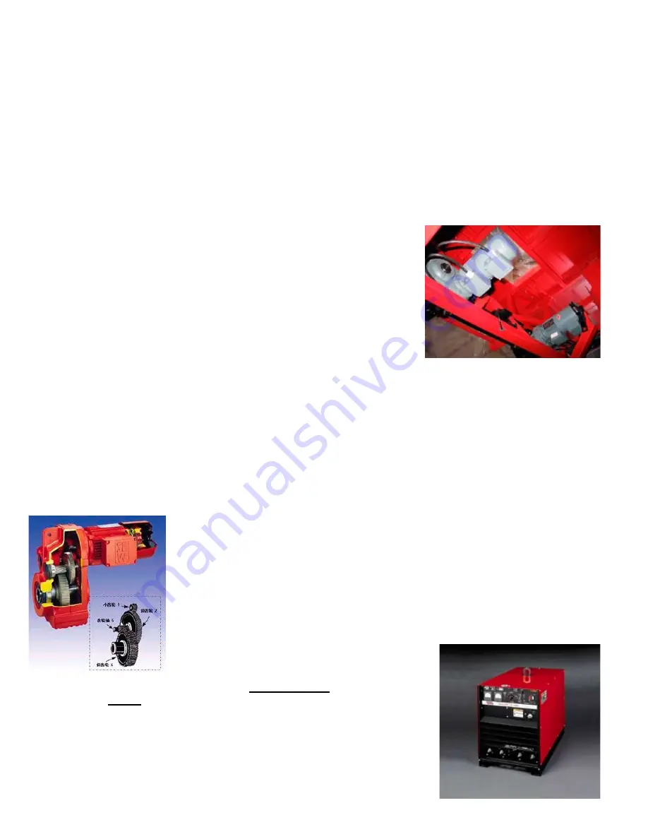
Each  single  flanged  drive  wheel  is  driven  by  an  individual  SAW  motor  / 

reducer to provide extra tracking force to prevent slipping that could cause 

weld defects. Drive motors are enclosed inside the frame top section with 

aluminum panel for good weather protection. 

Speeds for both motors are electronically synchronized and governed by an 

inverter for accurate speed travel. 

AC inverter: 

1.  Single-phase 220VAC input voltage 

2.   Automatic lift in torsion, 150% lift torsion in 6Hz. 

3.   Fully programmed & calibrated in factory 

4.   Soft PWM, running in low noise 

5.   15 speed, PID, 4-20 MA input 

6.   Provides RS-485 communication 

Caution: all the inverter drives inside the BGW control are pre-programmed before the girth welder is deliv-

ered to users on site. Please consult factory if re-programming is required. 

The SEW motors and reducer requires minimal maintenance with advantages of 

low noise & vibration, with 96% high efficiency through the reducer. It consists of 

a high rigid housing and spur gear; all parts are precisely machined with minimum 

tolerance for accurate travel mechanism. 

Welding Gear 

The standard welding equipment supplied is the Lincoln USA NA3 control and weld 

head fitted with nozzle, wire feed rolls, wire straightener, and 50lbs (23Kg) wire reels 

for feeding up to 3.2 mm (1/8’’) diameter wire. 

Lincoln USA DC600 is the standard power supply 

for the girth welder. Standard input power is 380V/3ph/50Hz and the line power 

requirement is 

40kVA. Other voltages and frequencies are available, please 

consult factory for details. 

Please refer to Lincoln’s NA3 and DC600 Instruction manuals for more informa-

tion on their welding equipment. 

Power supplies are installed on a steel storage case with the electrical cabinet 

for weather protection. 

Summary of Contents for BGW-1000

Page 1: ...1776 http www bugo com FAX 1 412 331 0383 Please record your equipment identification information below for future reference This information can be found on your machine nameplate Model Number Serial Number Date of Purchase Whenever you request replacement parts or information on this equipment always supply the information you have recorded above LIT BGW IPM 1209 ...

Page 2: ... 5 Never remove or bypass the equipment power cord ground Verify the equipment is grounded in accordance with all applicable local and national electrical safety codes If none exist use International Electric Code IEC 950 READ INSTRUCTIONS Read the instruction manual before installing and using the equipment 1 Do not plug in the power cord without first the verifying the equipment is OFF and the c...

Page 3: ...s as small as possible The larger the gap the higher the voltage and the higher the inter ference 5 Some plasma or welding units will inject high frequency interference into the AC power line Use separate power line branches whenever possible to power the plasma or welding source and the machine Do not plug them into the same outlet box 6 High frequency noise may enter the machine through the plas...

Page 4: ...n and Operations Master Control Connection 13 Installation and Operations Installation 14 Installation and Operations Input Connection 14 Installation and Operations Operation 15 Installation and Operations Welding 16 Welding Procedure Guidelines 16 Welding Procedure Guidelines Joint Design 16 Welding Procedure Guidelines Typical Welding Parameters 19 20 Troubleshooting 21 Maintenance 22 Girth Wel...

Page 5: ...The second side slave is hinged to the top of the master frame and is used when welding two sides The operator can move freely from one side of the machine to another by climbing up the ladder on one side to the common roof of the double sided machine A safety rail is provided at the roof of the main frame for safety purpose The BGW 2000 requires two welding power supplies Each unit has a flux rec...

Page 6: ...protection Speeds for both motors are electronically synchronized and governed by an inverter for accurate speed travel AC inverter 1 Single phase 220VAC input voltage 2 Automatic lift in torsion 150 lift torsion in 6Hz 3 Fully programmed calibrated in factory 4 Soft PWM running in low noise 5 15 speed PID 4 20 MA input 6 Provides RS 485 communication Caution All the inverter drives inside the BGW...

Page 7: ...3 control is the BGW master control Master Control The BGW master control houses the electronic travel inverter drive and associated control relays it provides a mean of integrated control of all the accessories of the girth welder eg flux vacuum 220V single phase aux outlet lamp flux winch The control panel includes all necessary control knobs and switches such as the speed control potentiometer ...

Page 8: ... must be in the travel position To operate manually the switch must be in the hand position Speed potentiometer R1 Accurately adjust speed travel speeds cm min of the girth welder The speed can be monitored at the control display U S version of Bug o All Time BGW would be programmed to display travel speed in IPM inch per minute Normal full speed travel switch Activate girth welder full speed trav...

Page 9: ...ould cause damage to the inverter It is not recommended to switch on the inverter again for at least three minutes after is it turned off Lighting switch Switch on the hurricane lamp for night operation Emergency Stop Push button stops all electronic functions including welding and travel Slave Control for BGWII double sided model ONLY Used at the slave side of the double sided girth welder it is ...

Page 10: ... vacuum for multi shifts continuous operation Such vacuum sys tems can be configured as follows to suitable various operation re quirements a Separator Filter mounted on top of the operator platform b Separator Filter mounted on frame roof vacuum system would move upward along with the roof and drive section of the BGW Electrical Cabinet Power Supply Storage The electrical cabinet of the girth wel...

Page 11: ...lation and setup is critical to ensure proper operation of the BGW and welding equipment Frame Setup Remove the machine from the crate A lifting device capable of lifting 4 409 lbs 2000 kg is required Place a crane hook to the lifting eye and carefully lift the machine upright CAUTION When lifting the double frame BGWII please use the four lifting eyes at the middle of the double sided frame drive...

Page 12: ...fixed right on top of the operator platform Adjust drive wheels of the travel mechanism to the diameters of the tank then lock them into position Fig Square tub mechanism Brief Introduction of Lifting Frame 1 Lifting mechanism adopts inside and outside annular tube structure which can complete in adjusting the length of frame by fixing or releasing location pin 2 Release the holddown screw of the ...

Page 13: ...the opened A frame of the double sided unit to straddle on the shell plate While loading the angle between the lifting cable and the horizon should not be greater than 60 The guide wheels should be extended to the maximum extension with the hand wheel and then bolted at the position perpendicular to the ground surface it provides a moving support to the frame and prevents impact between the flux b...

Page 14: ... NOTE Turn main input power of the machine OFF before performing reconnects procedure Failure to do so will result in damage to the machine Above non standard input at 240V 3ph 60Hz connection OPERATION After the BGW frame is securely straddled on the shell plate extend the guide wheel to support the weight of the frame and clear the flux belt from the tank wall for welding setup Adjust the flux b...

Page 15: ...h NA 3 to Auto Release the flux valve to allow sufficient amount of flux to drop on the arc start area and cover the wire stick out NOTE For models with electric flux valve option the flux would feed automatically when the wire touches the work when the operator presses inch down to feed wire prior welding Press start pushbutton of the NA3 and the start the weld sequence wire slowly feeds to the w...

Page 16: ... 450 480 19 20 5 in min 15 20 2nd 79 87 480 520 mm min 20 22 mm 28 31 450 520 20 26 in min 3rd 480 520 mm min 28 31 470 520 22 26 in min 4th 550 650 mm min 26 27 380 420 15 18 in min 1st 380 450 mm min 95 1 26 27 29 450 480 19 20 in min 15 20 2nd 24 32 mm 480 520 mm min 28 31 450 520 20 26 in min 3rd 500 650 mm min 28 31 480 520 22 26 in min 4th up 550 650 mm min Note The serviceability of a produ...

Page 17: ...380 25 26 28 in min 65 70 cm min B 1 5 12mm 380 25 26 28 in min 65 70 cm min F 1 5 12mm 360 24 25 28 30 in min 70 75 cm min B 1 5 12mm 350 24 25 28 30 in min 70 75 cm min A Shell Wall Thickness 4 10mm WTδ δ δ δ δ 10 Current A Voltage V Travel Speed F 1 4 10mm 360 380 25 26 28 30 in min 70 75 cm min B 1 4 10mm 360 26 28 30 in min 70 75 cm min F 2 4 10mm 380 24 25 30 31 in min 75 80 cm min B 2 4 10m...

Page 18: ...3 31 33 in min 80 85 cm min F 2 3 8mm 300 24 33 37 in min 85 95 cm min B 2 3 8mm 280 24 33 37 in min 85 95 cm min Note The serviceability of a product or structure utilizing the information in these guidelines must be the sole responsibly of the builder Many variables in design fabrication and service conditions affect the results obtained in applying this type of information ...

Page 19: ...is bad 3 Check 3 pin control cable Flux vacuum cannot operate 1 Bad vacuum relay in the control 1 Replace control relay switch 2 Vacuum itself is faulty 2 Replace flux vacuum Lamp is off 1 Bad lighting relay in the control 1 Replace relay switch 2 Control cable is loose or bad 2 Check control cable connector 3 Light bulb is bad 3 Replace light bulb Electric winch does not work 1 Control cable is l...

Page 20: ... feeding 1 Flux inlet valve is too close 1 Adjust and open up flux valve 2 Flux hose leakage 2 Repair or replace flux recovery hose Insufficient amount of flux 1 Suction nozzle is too far from the 1 Adjust suction head position is recovered weld 2 Wrong flux suction nozzle setup 2 Adjust suction head angle Flux belt is burnt by slag 1 Flux support belt too close to the 1 Adjust the distance to 6 9...

Page 21: ...tail maintenance instructions The serrated flanged drive wheel would need to be replaced if it is worn and loose the necessary grip to keep the girth welder travel steadily on the tank shells belt horizontal expansion mechanism Belt Replacement Procedure 1 Hold expansion top wheel against steel plate loosening screw bolt and screw nut as diagram indicates 2 Back out horizontal expansion mechanism ...

Page 22: ...W 1057 FENCE PROTECTION 23 1 BGW 1058 FLUX CONTAINER 24 1 BGW 1059 HOIST BRACKET 25 4 BGW 1061 FLAT WASHER 10 26 4 BGW 1062 SPRING WASHER 10 27 12 BGW 1063 HEX SOCKET SCREW M5X8 28 2 BGW 1064 HEAVY DUTY FLUX BLOWER 29 4 BGW 1066 LIGHT BRACKET 30 2 BGW 1067 LADDER 31 8 BGW 1068 REAR CLAMP 32 4 BGW 1069 FRAME HEIGHTADJUSTER 2 33 2 BGW 1071 REEL CONNECTOR 34 1 BGW 1072 AGW CONTROL 35 2 BGW 1073 AGW C...

Page 23: ...23 GIRTH WELDER EXPLODED VIEW 4 33 1100 mm 6 7 170 mm 13 6 345 mm 56 10 1425 mm 55 12 1400 mm 33 5 850 mm 33 5 850 mm 74 02 1880 mm 106 3 2700 mm ...

Page 24: ...BGW 1112 BUTTON SWITCH CP1 10R 01 7G 1 BGW 1113 TOGGLE SWITCH T 22 7H 1 BGW 1114 TOGGLE SWITCH T 23 7I 1 BGW 1115 EMERGENCY STOP BUTTON CE3T 10R 01 8 1 BGW 1116 FRONT PANEL 9 1 BGW 1019 POWER SWITCH CP E24 2 5 10 2 BGW 1021 DC CONTACTOR AL9 30 10 11 3 BGW 1017 RELAY CR M024DC2L M2SS P M42 12 1 BGW 1018 RELAY CR P110AC2L PSS P M42 13 3 BGW 1118 CABLE SLEEVE 5035 14A 9 BGW 1023 CONNECTOR WS32 4K 14B...

Page 25: ...25 CONTROL BOX ASSEMBLY EXPLODED VIEW ...

Page 26: ...Screw BGW 1177 1 7 Screw GB T77 1985 M6 4 1 BGW 1178 1 8 Nut Lid BGW 1179 1 9 Nut BGW 1181 1 10 Washer BGW 1182 1 11 Key BGW 1183 1 12 Hand Wheel 200 18 BGW 1184 1 13 Oil Seal BGW 1186 1 14 Bearing BGW 1187 2 15 Screw BGW 1188 2 16 Pin BGW 1189 1 17 Screw BGW 1191 1 18 Nut BGW 1192 1 19 Washer BGW 1193 1 20 Support Wheel 100 BGW 1194 1 21 Bearing 6202 BGW 1196 2 BGW 1087 GUIDE WHEEL ASSEMBLY PARTS...

Page 27: ...27 BGW 1087 GUIDE WHEEL ASSEMBLY EXPLODED VIEW 9 76 248 mm ...

Page 28: ...28 OPERATIONS SCHEMATIC ...

Page 29: ...29 WIRING DIAGRAM ...

Page 30: ...CHANTABILITYAND MAKES NO OTHER WARRANTY EXPRESSED OR IMPLIED BEYOND THE WARRANTY EXPRESSLY SET FORTH ABOVE BUYER S REMEDY FOR BREACH OF WARRANTY HEREUNDER SHALL BE LIMITED TO REPAIR OR REPLACEMENT OF NON CONFORMING PARTSAND MACHINES UNDER NO CIRCUMSTANCES SHALL CONSEQUENTIAL DAMAGES BE RECOVERABLE HOW TO OBTAIN SERVICE IF YOU THINK THIS MACHINE IS NOT OPERATING PROPERLY RE READ THE INSTRUCTION MAN...

Reviews: