Technical Data and Installation
- 2.18 -
ULTRAFEEDER
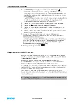
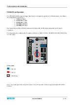
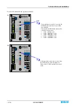
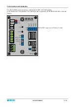
In this operating mode the INC/DEC LEDs signal the relevant input activation, corresponding to the 4
devices connected to the board PFU64/FS (GPR-1…GPR-4) or input activation corresponding to the 4
device Groups connected to the board PFU64/EXP (GPR-1…GPR-4).
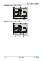
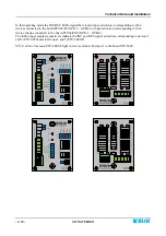
The following examples respectively indicate the INC and DEC signal activation corresponding to devices 2
and 3 (PFU/64FS) and to Groups 2 and 3 (PFU/64EXP)
NOTE: LEDs of the board
PFU/64EXP light in reverse mode with respect to the board PFU/64FS
Summary of Contents for ULTRAFEEDER
Page 1: ...ULTRAFEEDER YARN CONTROL SYSTEM Operating Manual ENGLISH Rev 4 1 February 2017 ...
Page 40: ...Technical Data and Installation 2 28 ULTRAFEEDER Page intentionally left blank ...
Page 72: ...ULTRAFEEDER Troubleshooting and Maintenance 4 6 ULTRAFEEDER Page intentionally left blank ...
Page 78: ...YTT Device 5 6 ULTRAFEEDER Page intentionally left blank ...


