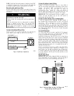
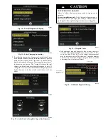
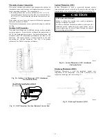
Bryant EVOLUTION V 189BNV 13 Installation Instructions Manual Download Page 20

20

FINAL CHECKS

IMPORTANT:

Before leaving job, be sure to do the

following:

1. Ensure that all wiring is routed away from tubing

and sheet metal edges to prevent rub--through or
wire pinching.

2. Ensure that all wiring and tubing is secure in unit

before adding panels and covers. Securely fasten
all panels and covers.

3. Tighten service valve stem caps to 1/12--turn past

finger tight.

4. Leave User’s Manual with owner. Explain system

operation and periodic maintenance requirements
outlined in manual.

5. Fill out Dealer Installation Checklist and place in

customer file.

CARE AND MAINTENANCE

For continuing high performance and to minimize
possible equipment failure, periodic maintenance must be

performed on this equipment.
Frequency of maintenance may vary depending upon

geographic areas, such as coastal applications. See

Owner’s Manual for information.
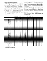
PURON

R

(R--410A) REFRIGERANT QUICK REFERENCE GUIDE

S

Puron refrigerant operates at 50--70 percent higher pressures than R--22. Be sure that servicing equipment and replacement components
are designed to operate with Puron refrigerant.

S

Puron refrigerant cylinders are rose colored.

S

Recovery cylinder service pressure rating must be 400 psig, DOT 4BA400 or DOT BW400.

S

Puron refrigerant systems should be charged with liquid refrigerant. Use a commercial type metering device in the manifold hose when
charging into suction line with compressor operating.

S

Manifold sets should be 700 psig high side and 180 psig low side with 550 psig low--side retard.

S

Use hoses with 700 psig service pressure rating.

S

Leak detectors should be designed to detect HFC refrigerant.

S

Puron refrigerant, as with other HFCs, is only compatible with POE oils.

S

Vacuum pumps will not remove moisture from oil.

S

Do not use liquid--line filter driers with rated working pressures less than 600 psig.

S

Do not leave Puron refrigerant suction line filter driers in line longer than 72 hours.

S

Do not install a suction--line filter drier in liquid--line.

S

POE oils absorb moisture rapidly. Do not expose oil to atmosphere.

S

POE oils may cause damage to certain plastics and roofing materials.

S

Wrap all filter driers and service valves with wet cloth when brazing.

S

A factory--approved liquid--line filter drier is required on every unit.

S

Do NOT use an R--22 TXV.

S

If indoor unit is equipped with an R--22 TXV or piston metering device, it must be changed to a hard--shutoff Puron refrigerant TXV.

S

Never open system to atmosphere while it is under a vacuum.

S

When system must be opened for service, recover refrigerant, evacuate then break vacuum with dry nitrogen and replace filter driers. . .
Evacuate to 500 microns prior to recharging.

S

Do not vent Puron refrigerant into the atmosphere.

S

Do not use capillary tube coils.

S

Observe all

warnings

,

cautions

, and

bold

text.

S

All indoor coils must be installed with a hard--shutoff Puron refrigerant TXV metering device.

Manufacturer reserves the right to discontinue, or change at any time, specifications or designs without notice and without incurring obligations.

E

Bryant Heating & Cooling Systems 7310 W. Morris St. Indianapolis, IN 46231

Edition Date: 11/17

Replaces: II189BNV--- 07

Catalog No. II189BNV---08

Summary of Contents for EVOLUTION V 189BNV 13

Page 1: ...nstall on Solid Level Mounting Pad 3 Step 3 Clearance Requirements 3 Step 4 Operating Ambient 4 Step 5 Elevate Unit 4 Step 6 Making Piping Connections 4 Step 7 Make Electrical Connections 5 Step 8 Com...

Page 2: ...erant equipment WARNING ELECTRICAL SHOCK HAZARD Failure to follow this warning could result in personal injury or death Before installing modifying or servicing system main electrical disconnect switc...

Page 3: ...or specific applications and for R 22 retrofit Step 1 Check Equipment and Job Site Unpack Unit Move to final location Remove carton taking care not to damage unit Inspect Equipment File claim with shi...

Page 4: ...eration Do not leave system open to atmosphere any longer than minimum required for installation POE oil in compressor is extremely susceptible to moisture absorption Always keep ends of tubing sealed...

Page 5: ...re to follow this caution may result in equipment damage or improper operation Never use the system compressor as a vacuum pump Refrigerant tubes and indoor coil should be evacuated using the recommen...

Page 6: ...g 189BNV models to non communicating 2 stage thermostats Use Fig 7 For required connections Unit is configured by factory for Evolution communicating control To wire unit for non communicating control...

Page 7: ...r on Control Board Jumper Wire Required for Single Stage C BLU YEL R RED BLK A160118 O O RVS Cooling O B W2 W1 W1 Heat Stage 3 W W1 W2 Heat Cool Stage 1 Y1 W2 Y1 Y1 Heat Cool Stage 2 Y Y2 Y Y2 Y2 Fan...

Page 8: ...non communicating furnaces set airflows to 350 400 cfm nominal ton in high stage and 70 80 percent of high stage airflow in low stage Step 9 Install Accessories No refrigeration circuit accessories ar...

Page 9: ...Select Line Set Length Vapor Line Diameter CAUTION UNIT OPERATION HAZARD Failure to follow this caution may result in improper unit operation For new installations only Add additional refrigerant due...

Page 10: ...nverter Motor Operational Control MOC then outputs the three phase PWM signal and frequency that gently ramps the compressor speed up to stage 2 and then will adjust to the demanded speed The gentle r...

Page 11: ...s to stabilize before declaring a properly charged system If the indoor temperature is below 70 F 21 11 C or the outdoor temperature is not in the favorable range adjust charge for line set length abo...

Page 12: ...g Mode 189BNV024B Fig 20 Charging in Cooling Mode 189BNV025 Fig 21 Charging in Cooling Mode 189BNV036 Fig 22 Charging in Cooling Mode 189BNV037 Fig 23 Charging in Cooling Mode 189BNV048 Fig 24 Chargin...

Page 13: ...tion of the procedure 2 Force system to operate in high stage by creating a large differential between room temperature and set point on thermostat Use multi meter to verify that 24 VAC is present bet...

Page 14: ...r NOTE A hissing sound may be heard during the equalization process This is normal TROUBLESHOOTING Systems Communication Failure If communication is lost with the User Interface UI the Green LED will...

Page 15: ...r low pressure lockout check the refrigerant charge and indoor airflow cooling Brown Out Protection If the line voltage is less than 187V for at least 4 seconds the Compressor and OD fan goes to 0 rpm...

Page 16: ...and distributor See Fig 31 for proper placement See Table 4 for proper resistances A14328 Fig 30 Outdoor Coil Thermistor OCT Attachment On Distributor Tube OAT Thermistor must be locked in place with...

Page 17: ...e Unit Size Resistance Ohms 13 24B 21 2 25 36 37 48 49 60 11 1 Status Codes Unit may occasionally become unresponsive due to certain combinations of previous fault codes There may not be anything wron...

Page 18: ...18 Utility Relay A13414 Fig 34 Variable Speed Control Board with optional Utility Relay...

Page 19: ...19 Table 6 Fault Codes...

Page 20: ...ig low side retard S Use hoses with 700 psig service pressure rating S Leak detectors should be designed to detect HFC refrigerant S Puron refrigerant as with other HFCs is only compatible with POE oi...

Reviews: