


14
NOTE
: The unit may be operated with an Evolution Connex
Control or a standard 2--stage thermostat. Evolution Connex
Control will utilize 5 stages cooling, while 2--stage thermostat will
only allow 2 discrete stages of cooling operation.
Variable Speed Compressor
This unit contains a variable speed rotary compressor that has a
wide operating range. It operates on a variable 3 phase sine wave
provided by the inverter. This compressor can only be operated by
the specific inverter supplied with the unit.
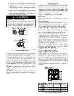
EQUIPMENT DAMAGE HAZARD
Failure to follow this caution may result in equipment damage
and/or improper operation.
Do not attempt to apply line voltage directly to the
compressor. This will destroy the compressor.
CAUTION
!
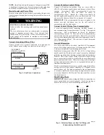
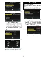
Field control Connections
For communicating operation use the communication Evolution
plug only. Only two wires, AB (color), are required. If necessary,
connect C for additional grounding (see Fig. 6). If using standard
2--stage thermostat, connect discrete inputs (R,C,Y2,Y1) for
2--stage control in cooling modes.
Pressure Transducer (SPT)
A 5 VDC output low pressure transducer that provides a 0--5 VDC
data for interpretation by the control board for a 0 to 200 psig
range of pressure at the suction tube. This interpreted pressure data
is then intelligently used by the AOC control board for low
pressure cut--out, loss of charge management, compressor
protection,
oil
circulation
management,
and
lubrication
management.
Pressure Equalizer Valve (PEV)
At the end of every compressor operation (after the 3.5 minute
Time Guard period), the equalizer valve opens for 150 seconds
plus an additional 15 seconds of protection before allowing the
compressor to start ramping up.
The PEV is located next to the suction and discharge of the
compressor.
The function of this valve is to prevent the
compressor from starting with a high refrigerant pressure
differential, thus helping the reliability of the compressor.
NOTE
: A hissing sound may be heard during the equalization
process. This is normal.
TROUBLESHOOTING
Systems Communication Failure
If communication is lost with the User Interface (UI), the Green
LED will be off. Check the wiring to the User Interface and the
indoor and outdoor units and power.
Model Plug
Each control board contains a model plug. The correct model plug
must be installed for the system to operate properly (see Table 3).
The model plug is used to identify the type and size of unit to the
control.
On new units, the model and serial numbers are inputted into the
AOC board’s memory at the factory. If a model plug is lost or
missing at initial installation, the unit will operate according to the
information input at the factory and the appropriate error code will
flash temporarily. An RCD replacement AOC board contains no
model and serial information. If the factory control board fails, the
model plug must be transferred from the original board to the
replacement board for the unit to operate.
When installing AC unit with older fan coils, a model plug change
may be required.
NOTE
:
The model plug takes priority over factory model
information input at the factory. If the model plug is removed after
initial power up, the unit will operate according to the last valid
model plug installed, and flash the appropriate fault code
temporarily.
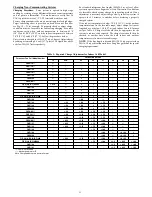
Table 3 – Factory Supplied Model Plug Information
189BNV
MODEL PLUG
NUMBER
PIN RESISTANCE
(K---ohms)
Pins 1---4
Pins 2---3
13
HK70EZ028
11K
180K
24B
HK70EZ010
5.1K
120K
25
HK70EZ011
5.1K
150K
36
HK70EZ012
5.1K
180K
37
HK70EZ025
11K
91K
48
HK70EZ013
5.1K
220K
49
HK70EZ027
11K
150K
60
HK70EZ014
5.1K
270K
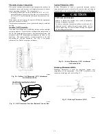
Service Tool
A150062
Fig. 27 -- Service Tool Connection
When working on the outdoor unit of a split system, the technician
would usually need to repeatedly walk between the indoor wall
control and the unit outside. To save time, the communicating
controls offer a service tool feature.
By wiring the service tool into the AOC board and powering it
with an external adapter, the technician can have a wall control
capable of running the system right at the outdoor unit.


