


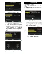


15
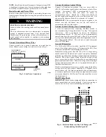
To use a service tool, connect the A and B communication bus
wires from this second communicating control to the terminals
marked A and B on the terminal strip located in the bottom left
corner of the AOC board (see Fig. 27). But instead of connecting
the wires on the service tool to the terminals marked C and D,
connect the C and D wires from the service tool to the 24V and C
on ST1 as shown in Fig. 27.
When the service tool is connected and powered up, the
communicating controls inside the home will ”go to sleep” and let
the service tool take control of the system. In this manner, the
service technician can run the diagnostic checkouts right at the
outdoor unit using the service tool.
After the checkouts are completed and it is no longer necessary to
use the service tool, remove it from the communicating controls
and the indoor communicating controls will regain control in about
two minutes.
Pressure Switch Protection
The outdoor unit is equipped with high pressure switch. If the
control senses the opening of a high pressure switch (open 600+/--5
psig, close 470+/--10 psig @77
_
F), it will respond as follows:
1. Display the appropriate fault code (see Table 6).
2. After a 6 minute delay, if there is a call for cooling and HPS
is reset, the PEV opens for 150 seconds to equalize system
pressures. The compressor and fan will then ramp to the
next lower stage of operation until demand is satisfied. In
the next call for cooling system will resume normal opera-
tion.
3. If the opened switch closes at any time after the 6 minute
delay, then the PEV opens for 150 seconds to equalize sys-
tem pressures. The compressor and fan will then ramp to the
next lower stage of operation until demand is satisfied. In
the next call for cooling system will resume normal opera-
tion.
4. If HPS trips when at lowest available stage, the unit opera-
tion is locked out for 4 hours.
5. In the event of a high--pressure switch trip or high--pressure
lockout, check the refrigerant charge, outdoor fan operation,
and outdoor coil (in cooling) for airflow restrictions.
6. In the event of a low--pressure trip or low--pressure lockout,
check the refrigerant charge and indoor airflow (cooling).
Brown--Out Protection
If the line voltage is less than 187V for at least 4 seconds, the
Compressor and OD fan goes to 0 rpm. Compressor and fan
operation are not allowed until voltage is a minimum of 190V. The
control will flash the appropriate fault code (see Table 6).
230V Line (Power Disconnect) Detection
The control board senses the presence of absence of 230V through
inverter feedback. Voltage should present at all times when system
is in service regardless if system is running or standby. If there is
no 230V at the inverter when the indoor unit is powered with a
cooling demand, the appropriate fault code is displayed on UI
(communicating only – see Table 6). If system is configured with
conventional thermostat (non--communicating), no fault code will
be displayed on AOC board, nor will any status LEDs be lit. Use
multimeter to check for the presence of 230V in this situation.
Temperature Thermistors
Thermistors are electronic devices which sense temperature. As the
temperature increases, the resistance decreases.
10Kohm
thermistors are used to sense outdoor air temperature (OAT), coil
temperature (OCT) and the suction line temperature (OST) located
between the reversing valve and the accumulator. A 50Kohm
thermistor is used to sense discharge temperature (ODT).
Refer to Table 4 and Fig. 28 and 29 for resistance values versus
temperature.
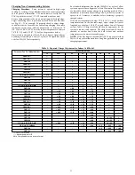
Table 4 – 10K/50Kohm Resistance Values vs Temperature
10Kohm
_
C (
_
F)
TEMPERATURE
RESISTANCE (ohms)
25.0 (77.0)
10.0 + / --- 2.3%
0.0 (32.0)
32.6 + / --- 3.2%
-28.0 (-18.4)
85.5 + / --- 3.4%
50Kohm
125.0 (257.0)
1.7 + / --- 1.6%
75.0 (167.0)
7.40 + / --- 2.0%
25.0 (77.0)
50.0 + / --- 2.3%
0
10
20
30
40
50
60
70
80
90
0
20
40
60
80
100
120
TEMPERATURE (DEG. F)
RESISTANCE (KOHMS)
THERMISTOR CURVE
A91431
Fig. 28 -- 10K Thermistor Resistance Versus Temperature
0
50
100
150
200
250
300
350
400
450
0
20
40
60
80
100
120
RE
SISTAN
CE (KOHM
S)
TEMPERATURE (
°
°
F)
50K THERMISTOR
A14022
Fig. 29 -- 50K Thermistor Resistance Versus Temperature
If the outdoor air or coil thermistor should fail, the control will
flash the appropriate fault code (see Table 6).
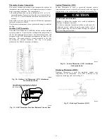
IMPORTANT:
The outdoor air thermistor, coil thermistor and
suction thermistor should be factory mounted in the final
locations.
Check to ensure thermistors are mounted properly
(See Fig. 30, 31, 32 and 33).


