


17
Variable Speed Compressor Winding Resistance
This compressor operates with 3--phase variable frequency PWM
variable voltage. For troubleshooting certain fault codes related to
compressor resistances, follow these steps:
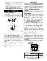
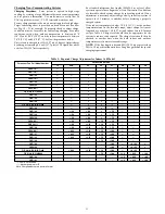
1. Disconnect compressor power leads from the inverter MOC
terminals, U (YEL), V (RED), and W (BLK).
2. Measure the resistance between YEL to RED, YEL to BLK,
and RED to BLK and compare to Table 5 values. Each re-
sistance set should be equal.
3. Measure the resistance to ground for each lead.
4. If the resistances check out, reconnect power leads to
appropriate terminal.
5. If the resistances appear to be abnormal, it will be necessary
to measure the resistance at the compressor fusite terminals.
6. During the removal of the compressor fusite cap, do not re-
move the RTV sealant. Remove the harness plug, measure
the resistances, and compare to Table 5.
7. Special care will need to be taken with the replacement of
the compressor fusite cap. Make sure the two holes in the
compressor fusite terminal box are still full of RTV sealant
before the cap is reinstalled. The factory RTV can be reused
as long as none of it has been removed during the cap
removal.
8. Reinstall compressor sound blanket making sure discharge
thermistor and compressor power harness are routed as they
were from the factory
Table 5 – Variable Speed Compressor Resistance
(winding resistance at 70
_
F
20
_
F)
WINDING
MODEL 189BNV (OHMs)
13, 24B
25
36
37, 48
49, 60
Between
terminals
1.13
.59
.59
.37
.24
Between
terminal &
ground
>1 mega
UNIT DAMAGE HAZARD
Failure to follow this caution may result in equipment damage
and/or improper operation.
Do not use Meggar for measuring the winding resistance.
CAUTION
!
UNIT DAMAGE HAZARD
Failure to follow this caution may result in equipment damage
and/or improper operation.
To maintain water integrity of the compressor fusite terminal
box, the two holes in outer ring need to be full of RTV sealant.
CAUTION
!
Fan Motor
If verification of proper operation is required for the fan motor
used in this unit, follow these steps:
1. Disconnect fan motor connector from control board.
2. Measure resistance between any 2 of the 3 leads present.
3. Compare measurement to values below
Fan Motor Resistance
Unit Size
Resistance (Ohms)
13, 24B
21.2
25, 36, 37, 48, 49, 60
11.1
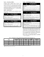
Status Codes
Unit may occasionally become unresponsive due to certain
combinations of previous fault codes. There may not be
anything wrong with the unit or components. The unit may
require a high voltage power cycling for at least 2 minutes or
longer to clear the condition. If the condition persists, conduct
further troubleshooting per Service Manual.
ATTENTION
!
Table 6 shows the status codes flashed by the amber status light.
Most system problems can be diagnosed by reading the status code
as flashed by the amber status light on the control board.
The codes are flashed by a series of short and long flashes of the
status light. The short flashes indicate the first digit in the status
code, followed by long flashes indicating the second digit of the
error code.
The short flash is 0.25 seconds ON and the long flash is 1.0 second
ON. Time between flashes is 0.25 seconds. Time between short
flash and first long flash is 1.0 second. Time between code
repeating is 2.5 seconds with LED OFF.
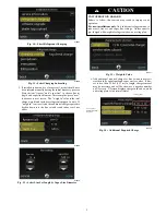
Codes are easily read from user interface (UI)
EXAMPLE
:
3 short flashes followed by 2 long flashes indicates a 32 code.
Table 6 shows this to be low pressure switch open.
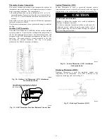
Status Code Recall Mode
Active status codes are stored in memory even when power is
absent. The most recent flashing status code (highest priority
active) can be recalled from memory via Status Code Recall Mode
and displayed using the amber LED. The Status Code Recall
Mode is accessed by shorting (use a clip wire) the “force defrost”
connector (labeled J2 on the board) and then power ON the unit.
Please make sure the unit is turned OFF before shorting the pins.
Status Code Recall Mode will continue as long as the “force
defrost” terminals remain shorted. The unit will not attempt to heat
or cool while the terminals remain shorted. Once the status code is
read, power--down the unit and remove the short.
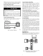
Utility Interface With Evolution Connex Control
The utility curtailment relay should be wired between the two
UTIL connections on the control board for this Evolution
Communicating System (see Fig. 34). This input allows a power
utility device to interrupt compressor operation during peak load
periods. When the utility sends a signal to shut the system down,
the User Interface status screen will display, ”Curtailment Yes”.
See UI installation instructions for setup details.


