


2
IMPORTANT
: Effective January 1, 2015, all split system and
packaged air conditioners must be installed pursuant to applicable
regional efficiency standards issued by the Department of Energy.
Information in these installation instructions pertains only to
189BNV series units.
SAFETY CONSIDERATIONS
Improper installation, adjustment, alteration, service, maintenance,
or use can cause explosion, fire, electrical shock, or other
conditions which may cause death, personal injury, or property
damage. Consult a qualified installer, service agency, or your
distributor or branch for information or assistance. The qualified
installer or agency must use factory--authorized kits or accessories
when modifying this product. Refer to the individual instructions
packaged with the kits or accessories when installing.
Follow all safety codes. Wear safety glasses, protective clothing,
and work gloves. Use quenching cloth for brazing operations.
Have fire extinguisher available. Read these instructions
thoroughly and follow all warnings or cautions included in
literature and attached to the unit. Consult local building codes and
current editions of the National Electrical Code (NEC) NFPA 70.
In Canada, refer to current editions of the Canadian electrical code
CSA 22.1.
Recognize safety information. This is the safety--alert symbol
!
!
When you see this symbol on the unit and in instructions or
manuals, be alert to the potential for personal injury. Understand
these signal words; DANGER, WARNING, and CAUTION. These
words are used with the safety--alert symbol. DANGER identifies
the most serious hazards which
will
result in severe personal injury
or death. WARNING signifies hazards which
could
result in
personal injury or death. CAUTION is used to identify unsafe
practices which
would
result in minor personal injury or product
and property damage. NOTE is used to highlight suggestions
which
will
result in enhanced installation, reliability, or operation.
CUT HAZARD
Failure to follow this caution may result in personal injury.
Sheet metal parts may have sharp edges or burrs. Use care and
wear appropriate protective clothing and gloves when
handling parts.
CAUTION
!
!
WARNING
UNIT OPERATION AND SAFETY HAZARD
Failure to follow this warning could result in personal injury
or equipment damage.
Puron
R
refrigerant systems operate at higher pressures than
standard R--22 systems. Do not use R--22 service equipment
or components on Puron
R
refrigerant equipment.
!
WARNING
ELECTRICAL SHOCK HAZARD
Failure to follow this warning could result in personal
injury or death.
Before installing, modifying, or servicing system, main
electrical disconnect switch must be in the OFF position.
There may be more than 1 disconnect switch. Lock out and
tag switch with a suitable warning label.
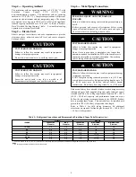
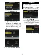
Indoor Thermostat Control Options
Model
Evolution Connex
Control
Standard
Thermostat
189BNV
Yes*
Yes**
* Requires model SYSTXBBECN01, SYSTXBBECC01 or SYSTXBBECW01
with version 11 software or newer.
* Version 12 software or newer required for model size 13.
** Using standard thermostat limits functionality of system.
!
WARNING
ELECTRICAL HAZARD -- HIGH VOLTAGE!
Failure to follow this warning could result in personal injury
or death.
Electrical components may hold charge. DO NOT remove
control box cover for 2 minutes after power has been
removed from unit.
PRIOR TO TOUCHING ELECTRICAL COMPONENTS:
Verify zero (0) voltage at inverter connections shown on
inverter cover.
EXPLOSION HAZARD
Failure to follow this warning could
result in death, serious personal injury,
and/or property damage.
Never use air or gases containing
oxygen for leak testing or operating
refrigerant compressors. Pressurized
mixtures of air or gases containing
oxygen can lead to an explosion.
!
WARNING
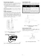
Inverter Cover
IMPORTANT:
The inverter cover should NEVER be removed
because there is no reason to remove the inverter cover to access
the inverter. The inverter has limited serviceability. Refer to
Service Manual for details on field replaceable parts.
A
replacement cover is provided with a replacement inverter.
INSTALLATION RECOMMENDATIONS
In some cases noise in the living area has been traced to gas
pulsations from improper installation of equipment.
1. Locate unit away from windows, patios, decks, etc. where
unit operation sound may disturb customer.
2. In noise sensitive applications (such as bedrooms), when a
lineset is mounted to ceiling joists or floor joists, the out-
door unit must be located at least 10 ft (3.05 m) away. If
this is not possible, create a line set configuration with
enough bends to provide 10 ft (3.05 m) of total line set
length outside the dwelling
3. Ensure that vapor and liquid tube diameters are appropriate
for unit capacity.
4. Run refrigerant tubes as directly as possible by avoiding un-
necessary turns and bends.
5. Leave some slack between structure and unit to absorb vi-
bration.
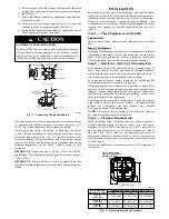
6. When passing refrigerant tubes through the wall, seal open-
ing with RTV or other pliable silicon--based caulk (see Fig.
1).
7. Avoid direct tubing contact with water pipes, duct work,
floor joists, wall studs, floors, and walls.


