


J.
Set Thermostat to Desired Room Temperature
Observe several operating cycles to verify proper operation.
K.
Review All Instructions
Review all instructions shipped with this boiler with owner or maintenance person. Instructions must be affixed on or adjacent to the boiler.
L.
Complete and Sign the Installation and Check-Out Certificate
CARE AND MAINTENANCE
NOTE:
Maintenance as outlined below can be performed by the owner unless otherwise noted.
The acidic nature of flue gases condensing on the aluminum boiler sections will cause the formation of aluminum oxide. This oxide formation is
normal, is generally uniform throughout the boiler sections, and represents a negligible mass of aluminum that is consumed by oxidation during
the life of the boiler. If left unchecked, this buildup may eventually cause blockage of the flue gas passages in the boiler sections, reducing
efficiency, and ultimately shutting down the boiler due to lack of combustion air flow. Regular service and maintenance by a qualified service
agency must be performed to assure safe trouble free operation and maximum efficiency.
PROCEDURE 1—BEGINNING OF EACH HEATING SEASON
WARNING: Disconnect electrical power to unit. Turn off gas supply to unit at the gas supply shutoff. Failure to do so
could result in fire, personal injury, property damage, or death.
1. Annual service call by a qualified service agency, which includes:
a. Examine flue passages between boiler sections, burner, and condensate lines, and clean if necessary following the annual examination
and cleaning instructions in
″
Annual Examination and Cleaning of Boiler Components
″
below.
b. Visually inspect venting and air intake system for proper function, deterioration or leakage. If the vent or air intake show any signs of
deterioration or leakage, repair or replace them immediately. Insure proper reassembly and resealing of the vent and air intake system.
c. Check for and remove any obstruction to the flow of combustion air or venting of flue gases. Check the air baffle located inside 1-1/2-in.
X 2-in. flexible coupling on the mixer, clean it if necessary and make sure to put it back. Refer to repair parts diagram of mixer and
pressure switch assembly for exact location.
d. Follow instructions for
″
Placing Boiler in Operation.
″
e. Follow instructions for
″
Check Out Procedure and Adjustments.
″
f. Visually inspect condensate drain line for proper operation and deterioration. Check for plugged condensate drain line.
g. Check the silicone rubber seals between boiler sections. Insure that there are no leaks. Use RTV silicone rubber adhesive sealant
(available in caulking gun tubes) rated for at least 400°F to replace or repair seals in locations where original seals have deteriorated.
h. Check all gasketed joints for leakage, and tighten bolts or replace gaskets if necessary.
i. Remove jacket front and top panels and check for piping leaks around relief valve and other fittings. Repair, if found. DO NOT use stop
leak compounds.
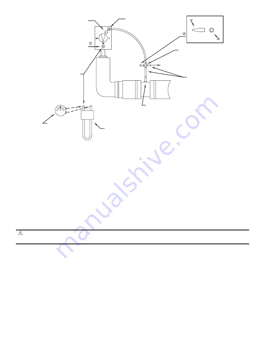
Fig. 22—Manifold Pressure Measurement Detail
A00313
PRESSURE
REGULATOR
ADJUSTMENT
(under cover screw)
GAS VALVE VENT
OUTLET PRESSURE TAP
(1/8” PLUG)
PRESSURE
DIFFERENTIAL
PRESSURE
GUAGE
U-TUBE
MANOMETER
REFERENCE PRESSURE
WHITE TRANSPARENT
VINYL TUBING
TO PRESSURE SWITCH
4 - WAY CONNECTOR
ROTOR CLAMP
VINYL CAP
—28—
Summary of Contents for BW9
Page 37: ...Fig 29 Troubleshooting Chart No 1 A00318 37 ...
Page 39: ...Fig 31 Troubleshooting Chart No 3 A00319 39 ...
Page 40: ...Fig 32 Troubleshooting Chart No 4 A00320 40 ...
Page 41: ...Fig 33 Troubleshooting Chart No 5 A00321 41 ...
Page 42: ...Fig 34 Troubleshooting Chart No 6 A00322 42 ...
Page 46: ...Fig 38 Boiler Block and Piping Assembly A99176 46 ...
Page 51: ... 51 ...
Page 52: ... 2003 CAC BDP 7310 W Morris St Indianapolis IN 46231 imbw9a03 52 Catalog No 63BW 9A4 ...