- 2 -
number in the GO TO column. Do whatever the ACTION says, then
proceed to the step indicated in the GO TO column.
If the ACTION is a question (a question will have a number in the
YES or NO column), answer it YES or NO. If the answer is YES, go
to the step indicated in the YES column. If the answer is NO, go to
the step indicated in the NO column.
Let’s try our guide out using the EXAMPLE section below, and see
how it works. Suppose that the problem is a defective low heat
pressure switch (for example the contacts will not open). This is an
internal problem and cannot simply be seen. We go to the START
HERE section to Step 1.
EXAMPLE
Start Here Section
STEP ACTION YES
NO
GO
TO
1.
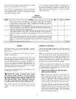
Step 1 tells us to remove main furnace door first and NOT TO REMOVE THE BLOWER
ACCESS PANEL. It then asks the question, “Is AMBER LED status light on?”. If the low
heat pressure switch was defective, a pressure switch did not open status code would be
flashing, so the answer is YES. We go to Step 2.
2 19
2.
Step 2 asks the question, “Is the AMBER LED status light blinking rapidly without a pause?”.
If the low heat pressure switch was defective, a pressure switch did not open status code would
be flashing, so the answer is NO. We go to Step 4.
3 4
4.
Step 4 asks the question, “Is the AMBER LED status light blinking ON/OFF slowly with a
combination of short and long flashes?”. If the low heat pressure switch was defective, a
pressure switch did not open status code would be flashing, so the answer is YES. We go to
Step 5.
5 7
5.
Step 5 tells us to determine the status code. The status code is a 2 digit number with the first
digit determined by the number of short flashes and the second digit by the number of long
flashes. So we count the short and long flashes and see that status code 23 is flashing and go to
Step 6.
6
6.
Step 6 tells us to go to status code 23 section
INDEX
GENERAL
The furnace must have a 115-vac power supply properly connected
and grounded. Correct polarity must be maintained to enable gas
heating operation.
The gas service pressure must not exceed 0.5 psig (14-in.wc), and no
less than 0.16 psig (4.5-in.wc).
Thermostat wire connections to the furnace at R and W/W1 are the
minimum required for gas heating operation. W2 must be connected
for 2-stage heating thermostats. Y/Y2 and G are required to be
connected to the furnace for single-stage cooling and heat pumps. Y1,
Y/Y2, and G are required for two-stage cooling and heat pumps. G is
required for continuous-fan. C
OM
-24V is required for some clock
thermostats. These connections must be made at the 24-vac terminal
block on the furnace control. (See Appendix A)
This furnace can be installed with either a single-stage heat/cool or a
two-stage heat/cool thermostat.
CAUTION: This furnace is equipped with a manual
reset switch in the gas control area. The switch will open
and shut off power to the gas valve, if a flame rollout or
overheating condition occurs in the gas control area. DO
NOT bypass the switch. Correct inadequate combustion-
air supply, component failure before resetting the switch.
Before operating the furnace, check each manual reset switch for
continuity. If necessary, press and release the button to reset the
switch.
SEQUENCE OF OPERATION
Using the schematic diagram in Appendix A, follow the sequence of
operation through the different modes. Read and follow the wiring
diagram very carefully.
Note:
If a power interruption occurs during a call for heat (W/W1 or
W/W1-and-W2), the control will start a 90-second blower-only ON
period two seconds after power is restored, if the thermostat is still
calling for gas heating. The amber LED light will flash code 12
during the 90-second period, after which the LED will be ON
continuous, as long as no faults are detected. After the 90-second
period, the furnace will respond to the thermostat normally.
The blower access panel must be installed for power to be conducted
through the blower door interlock switch ILK to the furnace control
CPU, transformer TRAN, inducer motor IDM, blower motor BLWM,
hot-surface igniter HSI, and gas valve GV.
1. SINGLE-STAGE THERMOSTAT AND TWO-STAGE
HEATING (ADAPTIVE MODE)
Note
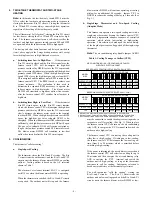
: The low-heat only switch SW1-2 selects either the low-
heat only operation mode when ON, (see item 2. below) or the
adaptive heating mode when OFF in response to a call for heat.
(See Fig. 1.) When the W2 thermostat terminal is energized it
will always cause high-heat operation when the R to W circuit
is closed, regardless of the setting of the low-heat only switch.
This furnace can operate as a two-stage furnace with a single-
stage thermostat because the furnace control CPU includes a
programmed adaptive sequence of controlled operation, which
selects low-heat or high-heat operation. This selection is based
upon the stored history of the length of previous gas-heating
periods of the single-stage thermostat.
!


