- 27 -
STEP ACTION YES
NO
GO
TO
15.
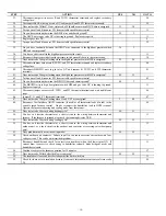
Replace the entire blower motor or blower control module attached to the blower motor. If
you replace the blower control module go to step 36. Always inspect failed motor for water
damage. If present, find source of water and fix it. Check A-coil and/or humidifier.
12
16.
Disconnect jumper wire across R and W/W1 thermostat terminals.
17
17.
Are all pins and wire leads intact on connectors between the variable speed furnace control and
the blower motor.
18 12
18.
Turn the power on and depress the door switch. Use a piece of tape to hold it closed.
19
19.
Do you have 115-vac across the BLACK blower motor wire connected to L1 and the WHITE
blower motor wire connected to NEUTRAL-L2?
21 20
20.
Replace the variable speed furnace control.
8
21.
Do you have 115-vac across the BLACK and WHITE power leads at the blower motor?
23
22
22.
You have an open wire or bad terminal on either the BLACK or WHITE wire between the
variable speed furnace control and the blower motor. If you have a power choke disconnect it
and check for continuity.
12
23.
Check the blower 12-vdc supply. To do this connect a DC voltmeter across terminals PL3-1
RED (+) and PL3-2 GREEN (-). Is there 12-vdc across the RED and GREEN blower wires?
24 20
24.
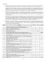
Connect a DC voltmeter across the RED (+) and GREEN (-) wires at connector PL13. Is there
12-vdc across the RED and GREEN blower wires?
26 25
25.
You have an open wire or bad terminal on either the RED or GREEN wire between connectors
PL3 and PL13. Repair it or replace harness.
8
26.
Check the blower motor serial input signal. To do this disconnect PL3 from the furnace
control and connect a DC voltmeter across terminals PL3-3 (+) and PL3-2 (-) on the variable
speed furnace control. Is there 5-vdc across PL3-3 and PL3-2?
Note:
The voltage should be very stable and should not fluctuate more than .02-vdc. If the
voltage fluctuates get a different volt meter before going on to the following steps.
Note:
Since the variable speed furnace control and the blower motor are continuously
communicating you do not actually need to run the blower motor to troubleshoot the PL3
connection.
27 20
27.
Reconnect PL3 to the variable speed furnace control and connect a DC voltmeter across
terminals PL3-3 YELLOW (+) and PL3-2 GREEN (-). Does the voltage appear to fluctuate
more than it did in step 26?
Note:
Typical voltmeters will show a fluctuation of .2-vdc to 1-vdc. The amount of
fluctuation is not important and you could see even more fluctuation depending on the
voltmeter you use.
28 20
28.
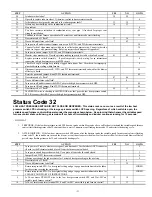
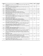
Check the blower motor serial output signal. To do this disconnect PL3 from the furnace
control and connect a DC voltmeter across terminals PL3-4 (+) and PL3-2 (-) on the variable
speed furnace control. The voltage should be near 0-vdc but it will fluctuate briefly several
times a second. If you have an analog voltmeter the needle will briefly go high several times a
second. If you have a digital voltmeter with a bar graph it will show a large change in
magnitude on the bar graph several times a second. If you have a plain digital voltmeter it will
show a brief fluctuation in voltage and the magnitude may vary depending on the volt meter
used.
Note:
Some voltmeters will not sense this fluctuation at all. Test your voltmeter on a known
good furnace prior to servicing this product.
Note:
You can also make a simple blinky light with a 1 K
Ω
resistor and an LED (RED works
best). These parts can be purchased at a nearby Radio Shack. The schematic is shown below:
29
When using the blinky light the LED will flash briefly several times a second when the blower
motor serial output signal is working properly. LED’s are directional and the lead closest to
the flat side goes to PL3-2.
1K
Ω
PL3-4 PL3-2


