- 10 -
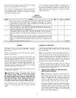
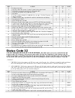
STEP ACTION YES
NO
GO
TO
26.
Is 115-vac across the transformer leads?
27
25
27.
Replace the transformer.
18
28.
Is 24-vac across W/W1 and C
OM
-24V on the variable speed furnace control?
You will not be able to check for voltage across W/W1 and C
OM
-24V if the furnace is
connected to a User Interface at the ABCD connector. Go to step 29.
30 29
29.
You have a defective thermostat, or a break in wiring between thermostat and furnace. Fix
problem.
18
30.
Disconnect all thermostat leads from the thermostat terminal block and jumper R to W/W1.
Does the furnace respond to the call for heat?
31 25
31.
You have an incompatible thermostat. Do any of the following:
1. Wire the thermostat C terminal to C
OM
-24V.
2. Isolate the W/W1 input with a relay.
3. Install ballast resistor across W/W1 and C
OM
-24V.
4. Replace the thermostat with a compatible model.
18
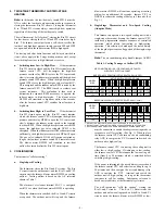
RAPID FLASHING AMBER LED - Indicates line voltage polarity is reversed, or the
transformers are out of phase in twinned units.
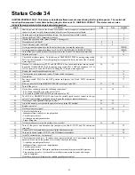
STEP ACTION YES
NO
GO
TO
1.
Is this furnace twinned with another furnace?
7
2
2.
Remove blower access panel and depress door switch. Use a piece of tape to hold switch
closed.
3
3.
Is 115-vac across NEUTRAL-L2 and chassis ground?
4
6
4.
Line voltage polarity is reversed. Fix problem.
5
5.
Go to page number indicated in Index for CLEANUP AND START-UP INSTRUCTIONS.
INDEX
6.
Replace the variable speed furnace control.
5
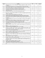
7.
Remove blower access panels and depress door switch in each unit. Use tape to hold switches
closed.
8
8.
Is the AMBER LED status light blinking rapidly in only one of the twinned units?
9
16
9.
Are the fuses, breakers, or manual disconnects to the problem unit correctly set?
11
10
10. Fix
problem.
5
11.
Are the Auxiliary Limit switches properly set?
12
10
12.
Do you have 115-vac across L1 and NEUTRAL-L2 in the problem unit?
13
15
13.
Do you have 24-vac across SEC-1 and SEC-2 in the problem unit?
6
14
14.
Replace the transformer.
5
15.
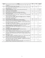
Turn power off to both units. Check continuity of power leads and door switch in the problem
unit. If necessary repair power leads and/or replace door switch in the problem unit.
5
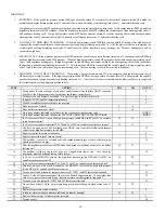
16.
Check the furnace circuit breaker location in the service panel.
On single-phase (residential) systems, each furnace circuit breaker should be located directly
across from each other in service panel, or each furnace circuit breaker should be located on
the same side of service panel, but must skip 1 space to be connected to the same leg of the 1-
phase power supply.
On 3-phase (commercial) systems, each furnace circuit breaker should be located directly
across from each other in service panel, or each furnace circuit breaker should be located on
the same side of service panel, but must skip 2 spaces to be connected to the same leg of the 3-
phase power supply.
17
17.
Check the 115-vac power lead connections at the variable speed furnace control of each
furnace. The BLACK lead goes to L1 and the WHITE lead goes to NEUTRAL-L2.
18
18.
Check the 115-vac transformer lead connections at the variable speed furnace control of each
furnace. The BLACK lead goes to L1 and the WHITE lead goes to NEUTRAL-L2.
19
19.
If the circuit breaker location and the 115-vac wiring is correct reverse the transformer
secondary lead connections SEC-1 and SEC-2 in the MAIN furnace.
5


