34
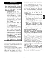
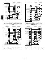
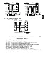
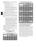
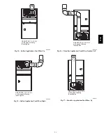
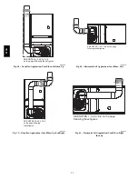
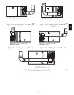
Venting Notes for Figures 34--46
1. For common vent, vent connector sizing and vent
material: United States----use the NFGC Canada----use the
CAN/CSA--B149.1--05
2. Immediately increase to 5--inch (127 mm) or 6--inch (152
mm) vent connector outside furnace casing when 5--inch
(127 mm) vent connector is required, refer to Note 1
above.
3. Side outlet vent for upflow and downflow installations
must use Type B vent immediately after exiting the
furnace, except when KGAVG0101DFG, Downflow Vent
Guard Kit, is used in the downflow position.
4. Type--B vent where required, refer to Note 1 above.
5. Four--inch single--wall (26 ga. min.) vent must be used
inside furnace casing and when the KGAVG0101DFG
Downflow Vent Guard Kit is used external to the furnace.
6. Accessory Downflow Vent Guard Kit, KGAVG0101DFG
required in downflow installations with lower vent
configuration.
7. Chimney Adapter Kit may be required for exterior
masonry chimney applications. Refer to Chimney Adapter
Kit, KGACA02014FC or KGACA02015FC, for sizing
and complete application details.
8. Secure vent connector to furnace elbow with (2)
corrosion--resistant
sheet
metal
screws,
spaced
approximately 180
_
apart.
9. Secure all other single wall vent connector joints with (3)
corrosion resistant screws spaced approximately 120
_
apart. Secure Type--B vent connectors per vent connector
manufacturer’s recommendations.
A04127
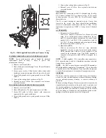
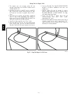
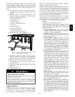
Fig. 47 -- Using Tin Snips to Cut Tie Points
313A
Summary of Contents for 313AAV
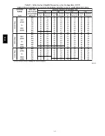
Page 41: ...41 Table 13 Orifice Size and Manifold Pressure In wc for Gas Input Rate A08220 313A...
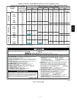
Page 42: ...42 Table 13 Orifice Size and Manifold Pressure In wc for Gas Input Rate CONT A08220A 313A...
Page 44: ...44 Table 14 Orifice Size And Manifold Pressure In wc For Gas Input Rate A08221 313A...

