


30
To prevent condensation in the furnace and vent system, the
following precautions must be observed:
1. The return--air temperature must be at least 60
_
F
(16
_
C)db except for brief periods of time during warm--up
from setback at no lower than 55
_
F (13
_
C) db or during
initial start--up from a standby condition.
2. Adjust the gas input rate per the installation instructions.
Low gas input rate causes low vent gas temperatures,
causing condensation and corrosion in the furnace and/or
venting system. Derating is permitted only for altitudes
above 2000 ft. (610 M).
3. Adjust the air temperature rise to the midpoint of the rise
range or slightly above. Low air temperature rise can cause
low vent gas temperature and potential for condensation
problems.
4. Set the thermostat heat anticipator or cycle rate to reduce
short cycling.
Air for combustion must not be contaminated by halogen
compounds which include chlorides, fluorides, bromides, and
iodides. These compounds are found in many common home
products such as detergent, paint, glue, aerosol spray, bleach,
cleaning solvent, salt, and air freshener, and can cause corrosion
of furnaces and vents. Avoid using such products in the
combustion--air supply. Furnace use during construction of the
building could cause the furnace to be exposed to halogen
compounds, causing premature failure of the furnace or venting
system due to corrosion.
Vent dampers on any appliance connected to the common vent
can cause condensation and corrosion in the venting system. Do
not use vent dampers on appliances common vented with this
furnace.
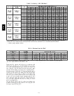
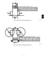
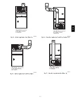
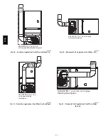
ADDITIONAL VENTING REQUIREMENTS
A 4” (101 mm) round vent elbow is supplied with the furnace. A
5--inch (127 mm) or 6-- inch (152 mm) vent connector may be
required
for
some
model
furnaces.
A
field--supplied
4--inch--to--5--inch (101 -- 127 mm) or 4--inch--to--6--inch (101 --
152 mm) sheet metal increaser fitting is required when 5--inch
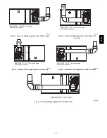
(127 mm) or 6--inch (152 mm) vent connector is used. See Fig.
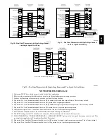
34--46 Venting Orientation for approved vent configurations.
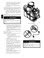
NOTE
: Vent connector length for connector sizing starts at
furnace vent elbow. The 4--inch vent elbow is shipped for upflow
configuration and may be rotated for other positions. Remove the
3 screws that secure vent elbow to furnace, rotate furnace vent
elbow to position desired, reinstall screws. The factory--supplied
vent elbow does NOT count as part of the number of vent
connector elbows.
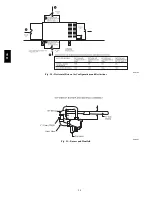
The vent connector can exit the door through one of 5 locations
on the door.
1. Attach the single wall vent connector to the furnace vent
elbow, and fasten the vent connector to the vent elbow
with at least two field--supplied, corrosion--resistant, sheet
metal screws located 180
_
apart.
NOTE
:
An accessory flue extension KGAFE0112UPH is
available to extend from the furnace elbow to outside the furnace
casing. If flue extension is used, fasten the flue extension to the
vent elbow with at least two field--supplied, corrosion--resistant,
sheet metal screws located 180
_
apart. Fasten the vent connector
to the flue extension with at least two field--supplied, corrosion
resistant sheet metal screws located 180
_
apart.
2. Vent the furnace with the appropriate connector as shown
in Fig. 34--46.
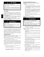
CUT HAZARD
Failure to follow this caution may result in personal injury.
Sheet metal parts may have sharp edges or burrs. Use care
and wear appropriate protective clothing, safety glasses and
gloves when handling parts and servicing furnaces.
CAUTION
!
3. Orient the door to determine the correct location of the
door cutout to be removed.
4. Use aviation--type tin snips to remove the correct
U--shaped cut--out in door.
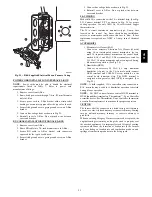
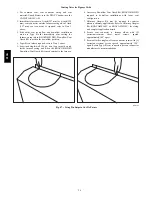
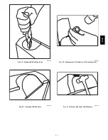
NOTE
: If this furnace is equipped with knockouts in the door
for the vent, a number of techniques can be used to remove these
knockouts as seen in Fig. 47 through 51. The knockout in the
bottom of the door is unique due to its flanging and is not easily
removed by first cutting the two tie points at the edge of the door,
using aviation--type tin snips. (See Fig. 47.) A sharp blow to the
rounded end of the knockout (See Fig. 48.) will separate more tie
points and allow the knockout to be pulled loose. (See Fig. 49.)
Remove all burrs and sharp edges. For the knockouts in the other
locations on the door (top and sides), tin snips can also be used
along the door edges; however, the preferred method is to use a
hammer and screwdriver to strike a sharp blow (See Fig. 50.)
directly to the knockout tie points or use a hammer in the upper
left corner of the desired knockout. (See Fig. 51.) Remove all
burrs and sharp edges.
BURN HAZARD
Failure to follow this caution may cause personal injury.
Hot vent pipe is within reach of small children when
installed in downflow position. See the following
instruction.
CAUTION
!
An accessory Vent Guard Kit, KGAVG0101DFG is REQUIRED
for downflow applications for use where the vent exits through
the lower portion of the furnace casing door. Refer to the Vent
Guard Kit Instructions for complete details.
The horizontal portion of the venting system shall slope upwards
not less than 1/4--in. per linear ft. (21 mm/M) from the furnace to
the vent and shall be rigidly supported every 5 ft. (2 M) or less
with metal hangers or straps to ensure there is no movement after
installation.
SIDEWALL VENTING
This furnace is not approved for direct sidewall horizontal
venting.
In the U.S
.: Per section 12.4.3.1 of the NFPA54/ANSI
Z223.1--2006, any listed mechanical venter may be used, when
approved by the authority having jurisdiction.
In Canada
: Per section 8.24.2 of the CAN/CSA--B149.1--05,
any listed venters may be used, when approved by the authority
having jurisdiction.
Select the listed mechanical venter to match the Btuh input of the
furnace being vented. Follow all manufacturer’s installation
requirements for venting and termination included with the listed
mechanical venter.
313A
Summary of Contents for 313AAV
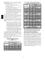
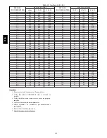
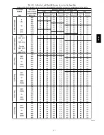
Page 41: ...41 Table 13 Orifice Size and Manifold Pressure In wc for Gas Input Rate A08220 313A...
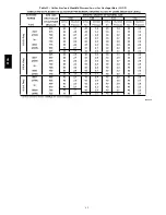
Page 42: ...42 Table 13 Orifice Size and Manifold Pressure In wc for Gas Input Rate CONT A08220A 313A...
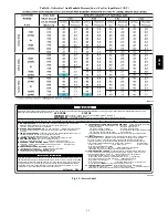
Page 44: ...44 Table 14 Orifice Size And Manifold Pressure In wc For Gas Input Rate A08221 313A...


