


38
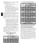
c. Measure time (in sec) for gas meter to complete 1
revolution and note reading. The 2 or 5 cubic feet dial
provides a more accurate measurement of gas flow.
d. Refer to Table 12 for cubic ft. of gas per hr.
e. Multiply gas rate (cu ft./hr) by heating value (Btuh/cu ft.)
to obtain input.
If clocked rate does not match required input from Step 1,
increase manifold pressure to increase input or decrease manifold
pressure to decrease input. Repeat steps b through e until correct
input is achieved. Reinstall regulator seal cap on gas valve.
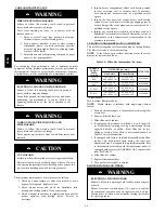
5. Set temperature rise. The furnace must operate within the
temperature rise ranges specified on the furnace rating
plate. Do not exceed temperature rise range specified on
unit rating plate. Determine the temperature rise as
follows:
NOTE
: Blower access door must be installed when taking
temperature rise reading. Leaving blower access door off will
result in incorrect temperature measurements.
ELECTRICAL SHOCK HAZARD
Failure to follow this warning could result in personal injury
or death.
Disconnect 115--v electrical power before changing speed
tap.
!
WARNING
a. Place thermometers in return and supply ducts as close
to furnace as possible. Be sure thermometers do not see
radiant heat from heat exchangers. Radiant heat affects
temperature rise readings. This practice is particularly
important with straight--run ducts.
b. When thermometer readings stabilize, subtract return--air
temperature from supply--air temperature to determine air
temperature rise.
NOTE
:
Blower access door must be installed for proper
temperature rise measurement.
NOTE
: If the temperature rise is outside this range, first check:
(1.) Gas input for heating operation.
(2.) Derate for altitude if applicable.
(3.) Return and supply ducts for excessive restrictions
causing static pressures greater than 0.50--in. wc.
(4.) Dirty filter.
c. Reinstall blower access door if removed.
d. Turn gas valve ON/OFF switch to ON.
e. Adjust air temperature rise by adjusting blower speed.
Increase blower speed to reduce temperature rise.
Decrease blower speed to increase temperature rise
f. Turn thermostat down below room temperature and
remove blower access door.
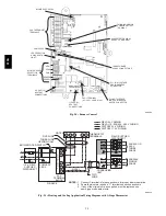
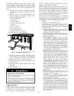
g. To change motor speed selection for heating, remove
blower motor lead from control HEAT terminal (See Fig.
24.) Select desired blower motor speed lead from one of
the other terminals and relocate it to the HEAT terminal
(See Table 11 for lead color identification). Reconnect
original lead to SPARE terminal.
h. Repeat steps a through e.
i. When correct input rate and temperature rise is achieved,
turn gas valve ON/OFF switch to OFF.
j. Remove manometer or similar device from gas valve.
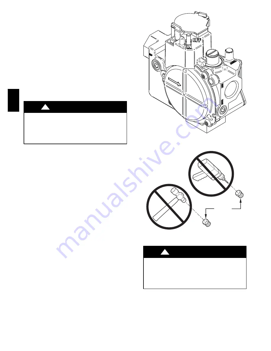
k. Reinstall manifold pressure tap plug in gas valve.
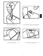
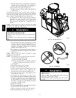
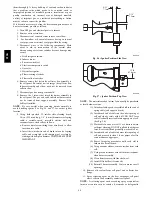
A06666
Fig. 52 -- Gas Control Valve
BURNER
ORIFICE
A93059
Fig. 53 -- Orifice Hole
FIRE HAZARD
Failure to follow this warning could result in personal
injury, death, and/or property damage.
Reinstall manifold pressure tap plug in gas valve to prevent
gas leak.
!
WARNING
313A
Summary of Contents for 313AAV
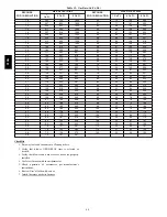
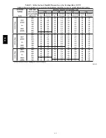
Page 41: ...41 Table 13 Orifice Size and Manifold Pressure In wc for Gas Input Rate A08220 313A...
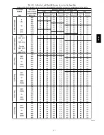
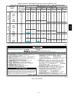
Page 42: ...42 Table 13 Orifice Size and Manifold Pressure In wc for Gas Input Rate CONT A08220A 313A...
Page 44: ...44 Table 14 Orifice Size And Manifold Pressure In wc For Gas Input Rate A08221 313A...


