Bryant 313AAV Installation, Start-Up, Operating And Service And Maintenance Instructions Download Page 49

49

hydrocarbons or inadequate seal may occur) and RTV sealant
(G.E. 162, 6702, or Dow--Corning 738) are needed before
starting installation. DO NOT substitute any other type of RTV
sealant. G.E. 162 (P771--9003) is available through RCD in 3--oz.
tubes.

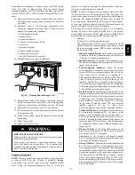
12. Apply new sealant to flange of collector box and attach to

cell panel using existing screws, making sure all screws
are secure.

13. Reconnect wires to the following components. (Use

connection diagram on wiring label, if wires were not
marked for reconnection locations.):

a. Draft safeguard switch.

b. Inducer motor.

c. Pressure switch(es).

d. Limit over--temperature switch.

e. Gas valve.

f. Hot surface igniter.

g. Flame--sensing electrode.
h. Flame rollout switches.

i. Install NOx baffles (if removed).

14. Reinstall internal vent pipe, if applicable.
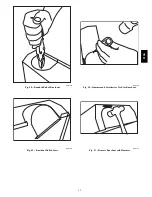
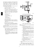
A91252

Fig. 58 -- Cleaning Heat Exchanger Cell

15. Reinstall vent connector on furnace vent elbow. Securely

fasten vent connector to vent elbow with 2 field--supplied,
corrosion--resistant, sheet metal screws located 180

_

apart.

16. Replace blower access door only, if it was removed.
17. Set thermostat above room temperature and check furnace

for proper operation.

18. Verify blower airflow and speed changes between heating

and cooling.

19. Check for gas leaks.
20. Replace outer access door.

FIRE OR EXPLOSION HAZARD

Failure to follow this warning could result in personal injury,

death and/or property damage.
Never purge a gas line into a combustion chamber. Never

test for gas leaks with an open flame. Use a commercially

available soap solution made specifically for the detection of

leaks to check all connections.

!

WARNING

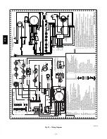
Sequence of Operation
NOTE

: Furnace control must be grounded for proper operation

or control will lock out. Control is grounded through
green/yellow wire routed to gas valve and manifold bracket
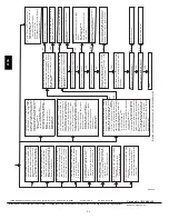
screw. Using the schematic diagram in Fig. 59, follow the

sequence of operation through the different modes. Read and
follow the wiring diagram very carefully.

NOTE

: If a power interruption occurs during a call for heat (W),

the control will start a 90--second blower--only ON period two
seconds after power is restored, if the thermostat is still calling for
gas heating. The Amber LED light will flash code 12 during the
90--second period, after which the LED will be ON continuous,
as long as no faults are detected. After the 90--second period, the
furnace will respond to the thermostat normally.
The blower door must be installed for power to be conducted
through the blower door interlock switch ILK to the furnace

control CPU, transformer TRAN, inducer motor IDM, blower

motor BLWM, hot--surface igniter HSI, and gas valve GV.

1. Heating

(See Fig. 25 for thermostat connections.)
The wall thermostat “calls for heat,” closing the R--to--W
circuit. The furnace control performs a self--check, verifies

the pressure switch contacts PRS are open, and starts the
inducer motor IDM.

a.

Inducer Prepurge Period

-- As the inducer motor IDM

comes up to speed, the pressure switch contacts PRS close
to begin a 15--second prepurge period.

b.

Igniter Warm--Up

-- At the end of the prepurge period,

the Hot--Surface igniter HSI is energized for a 17--second

igniter warm--up period.

c.

Trial--for--Ignition Sequence

-- When the igniter

warm--up period is completed, the main gas valve relay

contacts GVR close to energize the gas valve GV, the gas
valve opens, and 24 vac power is supplied for a

field--installed humidifier at the HUM terminal. The gas
valve GV permits gas flow to the burners where it is

ignited by the HSI. Five seconds after the GVR closes,
a 2--second flame proving period begins. The HSI igniter
will remain energized until the flame is sensed or until the

2--second flame proving period begins.

d.

Flame--Proving

-- When the burner flame is proved at the

flame--proving sensor electrode FSE, the furnace control
CPU begins the blower--ON delay period and continues
to hold the gas valve GV open. If the burner flame is not

proved within two seconds, the control CPU will close
the gas valve GV, and the control CPU will repeat the

ignition

sequence

for

up

to

three

more

Trials--For--Ignition before going to Ignition--Lockout.

Lockout will be reset

automatically after three hours or

by momentarily interrupting 115 vac power to the
furnace, or by interrupting 24 vac power at SEC1 or

SEC2 to the furnace control CPU (not at W, G, R, etc.).
If flame is proved when flame should not be present, the

furnace control CPU will lock out of Gas--Heating mode
and operate the inducer motor IDM until flame is no
longer proved.

e.

Blower--On Delay

-- If the burner flame is proven, the

blower motor is energized on HEAT speed 25 seconds

after the gas valve GV is energized.
Simultaneously, the electronic air cleaner terminal
EAC--1 is energized and remains energized as long as the

blower motor BLWM is energized.

f.

Blower--Off Delay

-- When the thermostat is satisfied, the

R--to--W circuit is opened, de--energizing the gas valve
GV, stopping gas flow to the burners, and de--energizing
the humidifier terminal HUM. The inducer motor IDM

will remain energized for a 5--second post--purge period.
The blower motor BLWM and air cleaner terminal

EAC--1 will remain energized for 90, 120, 150, or 180
seconds (depending on the blower--OFF delay selection).

The furnace control CPU is factory--set for a 120--second
blower--OFF delay.

313A

Summary of Contents for 313AAV

Page 1: ...lter Arrangement 14 Air Ducts 14 Gas Piping 17 115 V Wiring 22 START UP ADJUSTMENT AND SAFETY CHECK 36 General 36 Start up Procedures 36 Adjustments 36 Check Safety Controls 39 Checklist 40 SERVICE AN...

Page 2: ...11 16 322 9 5 16 237 4 102 114 52 16 406 070 16 048070 17 1 2 445 15 7 8 403 16 406 11 9 16 294 4 102 136 62 16 406 090 16 048090 21 533 19 3 8 492 19 1 2 495 13 5 16 338 4 102 150 68 20 508 110 20 0...

Page 3: ...e space containing the furnace the return air shall also be handled by duct s sealed to the furnace casing and terminating outside the space containing the furnace See Air Ducts section 8 A gas fired...

Page 4: ...local codes the installation must comply with the national codes listed below and all authorities having jurisdiction In the United States and Canada follow all codes and standards for the following...

Page 5: ...Z223 1 2006 Chapters 12 and 13 S CANADA CAN CSA B149 1 05 Part 8 and Appendix C ELECTROSTATIC DISCHARGE ESD PRECAUTIONS PROCEDURE FURNACE RELIABILITY HAZARD Improper installation or service of furnace...

Page 6: ...eaning Always comply with minimum fire protection clearances shown on the furnace clearance to combustible label The following types of furnace installations may require OUTDOOR AIR for combustion due...

Page 7: ...It also prevents the entrainment of drywall dust into combustion air which can cause fouling and plugging of furnace components The temperature of the return air to the furnace is maintained between 5...

Page 8: ...h means to prevent operation of either unit unless the damper is in the full heat or full cool position AIR FOR COMBUSTION AND VENTILATION Provisions for adequate combustion ventilation and dilution a...

Page 9: ...ilation and dilution of flue gases The furnace combustion air supply must be provided in accordance with this instruction manual WARNING The Standard Method 1 The space has no less volume than 50 cubi...

Page 10: ...ly and 3 Outdoor openings shall be sized as follows a Calculate the Ratio of all Indoor Space volume divided by required volume for Indoor Combustion Air Method below A02098 Fig 9 Removing Bottom Clos...

Page 11: ...commended that the perforated supply air duct flanges be completely folded over or removed from furnace when installing the furnace on a factory supplied cased coil or coil box To remove the supply ai...

Page 12: ...12 APPROVED COIL ASSEMBLY OR COIL BOX FURNACE SHEET METAL PLENUM FLOOR OPENING COMBUSTIBLE FLOORING A08556 Fig 13 Furnace Plenum and Coil Assembly or Coil Box Installed on a Combustible Floor 313A...

Page 13: ...y damage Do not install the furnace on its back or hang furnace with control compartment facing downward Safety control operation will be adversely affected Never connect return air ducts to the back...

Page 14: ...d and sealed to enhance system performance When air conditioning is used a vapor barrier is recommended Maintain a 1 in 25 mm clearance from combustible materials to supply air ductwork for a distance...

Page 15: ...THREADED ROD 4 REQ SECURE ANGLE IRON TO BOTTOM OF FURNACE WITH 3 8 x3 4 19mm SCREWS TYPICAL FOR 2 SUPPORTS 1 25mm SQUARE 1 1 4 x1 1 4 x1 8 32x32x3mm ANGLE IRON OR UNI STRUT MAY BE USED 2 HEX NUTS 2 WA...

Page 16: ...Suspension with Straps 30 IN 762mm MIN WORK AREA 6 MIN TYPE B VENT 17 3 4 22 SHEET METAL SEDIMENT TRAP EQUIPMENT MANUAL SHUT OFF GAS VALVE LINE CONTACT ONLY PERMISSIBLE BETWEEN LINES FORMED BY INTERSE...

Page 17: ...xtend a minimum of 2 in 51 mm outside the furnace WARNING Gas piping must be installed in accordance with national and local codes Refer to current edition of NFGC in the U S the CAN CSA B149 1 05 in...

Page 18: ...ded 3 4 in 19 mm washable filter media such as contained in factory authorized accessory filter rack To determine airflow performance without this filter assume an additional 0 1 in wc available exter...

Page 19: ...19 A02075 Fig 18 Upflow Return Air Configurations and Restrictions A02163 Fig 19 Downflow Return Air Configurations and Restrictions 313A...

Page 20: ...20 A02162 Fig 20 Horizontal Return Air Configurations and Restrictions 2 51mm Street Elbow A08551 Fig 21 Burner and Manifold 313A...

Page 21: ...nt ELECTRICAL CONNECTIONS ELECTRICAL SHOCK HAZARD Failure to follow this warning could result in personal injury or death Blower access panel door switch opens 115 v power to control No component oper...

Page 22: ...Step 1 5 Route J Box wires within furnace away from sharp edges rotating parts and hot surfaces ELECTRICAL CONNECTION TO J BOX Field Supplied Electrical Box on Furnace J Box Bracket See Fig 23 1 Remov...

Page 23: ...t is required use ONLY a 3 amp fuse of identical size ACCESSORIES 1 Electronic Air Cleaner EAC Connect an accessory Electronic Air Cleaner if used using 1 4 in female quick connect terminals to the tw...

Page 24: ...AUXILIARY J BOX 24 V TERMINAL BLOCK THREE WIRE HEATING ONLY FIVE WIRE NOTE 1 NOTE 2 FIELD SUPPLIED DISCONNECT CONDENSING UNIT TWO WIRE FURNACE C O N T R O L R G COM W C R G Y GND GND FIELD 24 V WIRING...

Page 25: ...nce with ANSI Z21 47 2006 CSA 2 3 2006 and operate with a non positive vent static pressure to minimize the potential for vent gas leakage Category I furnaces operate with a flue loss not less than 17...

Page 26: ...wing these figures A04216 Fig 27 Single Stage Furnace with Two Speed Air Condi tioner See notes 1 2 4 6 7 9 10 and 12 on the page following these figures A04217 Fig 28 Single Stage Furnace with Single...

Page 27: ...installations This is factory default 5 Dip switch No 1 on Thermidistat should be set in ON position for heat pump installations 6 Dip switch No 2 on Thermidistat should be set in OFF position for sin...

Page 28: ...erior Masonry Chimney FAN NAT Installations with Type B Double Wall Vent Connectors NFPA AGA Table 8 Combined Appliance Maximum Input Rating in Thousands of BTUH per Hour VENT HEIGHT FT M INTERNAL ARE...

Page 29: ...n cleanout Mortar tile metal vent fuel oil residue Is liner and top seal in good condition Is chimney property lined with clay tile liner Crown condition Missing mortar or brick Rebuild crown Yes Yes...

Page 30: ...sing If flue extension is used fasten the flue extension to the vent elbow with at least two field supplied corrosion resistant sheet metal screws located 180_ apart Fasten the vent connector to the f...

Page 31: ...8 9 on the pages following these figures A03209 Fig 35 Upflow Application Vent Elbow Right SEE NOTES 1 2 3 4 5 7 8 9 on the page following these figures A03210 Fig 36 Downflow Application Vent Elbow...

Page 32: ...9 on the page following these figures A03212 Fig 39 Downflow Application Vent Elbow Up then Right SEE NOTES 1 2 4 7 8 9 on the page following these figures A03213 Fig 40 Horizontal Left Application V...

Page 33: ...15 Fig 43 Horizontal Left Application Vent Elbow Up SEE NOTES 1 2 4 5 7 8 9 on the page following these figures A03219 Fig 44 Horizontal Right Application Vent Elbow Left then Up SEE NOTES 1 2 4 5 7 8...

Page 34: ...min vent must be used inside furnace casing and when the KGAVG0101DFG Downflow Vent Guard Kit is used external to the furnace 6 Accessory Downflow Vent Guard Kit KGAVG0101DFG required in downflow ins...

Page 35: ...35 A04128 Fig 48 Rounded End of Knockout A04129 Fig 49 Knockout Pulled Loose A04130 Fig 50 Hammer and Screwdriver Used for Knockout A04131 Fig 51 Remove Knockout with Hammer 313A...

Page 36: ...rned on See Fig 24 ELECTRICAL SHOCK HAZARD Failure to follow this warning could result in personal injury or death Blower access door switch opens 115 v power to control No component operation can occ...

Page 37: ...right then up Fig 41 132 000 5 127 7 2 Horizontal Left Vent elbow right Fig 42 132 000 5 127 7 2 NOTE All vent configurations must also meet National Fuel Gas Code venting requirements NFGC 4 in 102 m...

Page 38: ...rmometer readings stabilize subtract return air temperaturefromsupply air temperatureto determineair temperature rise NOTE Blower access door must be installed for proper temperature rise measurement...

Page 39: ...ion during this test cause must be determined and corrected a Run furnace for at least 5 minutes b Gradually block off return air with a piece of cardboard or sheet metal until the limit trips c Unblo...

Page 40: ...8 621 78 46 92 231 30 120 240 600 80 45 90 225 31 116 232 581 82 44 88 220 32 113 225 563 84 43 86 214 33 109 218 545 86 42 84 209 34 106 212 529 88 41 82 205 35 103 206 514 90 40 80 200 36 100 200 50...

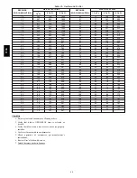
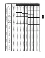
Page 41: ...41 Table 13 Orifice Size and Manifold Pressure In wc for Gas Input Rate A08220 313A...

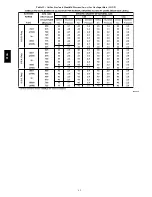
Page 42: ...42 Table 13 Orifice Size and Manifold Pressure In wc for Gas Input Rate CONT A08220A 313A...

Page 43: ...he furnace from heating The control system also requires an earth ground for proper operation of the control and flame sensing electrode The 24 v circuit contains an automotive type 3 amp fuse located...

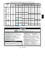
Page 44: ...44 Table 14 Orifice Size And Manifold Pressure In wc For Gas Input Rate A08221 313A...

Page 45: ...or before initiating status code recall After status code recall is completed component test will occur 327596 101 REV B 31 PRESSURE SWITCH DID NOT CLOSE OR REOPENED If open longer than five minutes i...

Page 46: ...service agency 5 Inspect the vent pipe vent system before each heating season for rust corrosion water leakage sagging pipes or broken fittings Have vent pipes vent system serviced by a qualified serv...

Page 47: ...er housing and set screw contacts the flat portion of the motor shaft Loosen set screw on blower wheel and reposition if necessary 14 Spin the blower wheel by hand to verify that the wheel does not ru...

Page 48: ...rifle cleaning brush 36 in 914 mm long 1 4 6 mm diameter steel spring cable a variable speed reversible electric drill and vacuum cleaner clean cells as follows a Remove metal screw fitting from wire...

Page 49: ...ormer TRAN inducer motor IDM blower motor BLWM hot surface igniter HSI and gas valve GV 1 Heating See Fig 25 for thermostat connections The wall thermostat calls for heat closing the R to W circuit Th...

Page 50: ...R to G and Y Y2 circuit is closed and there is a demand for dehumidification the furnace blower motor BLWM will drop the blower speed from COOL to HEAT for a maximum of 10 minutes before reverting bac...

Page 51: ...d Y Y2 and G R to W and Y1 and Y Y2 or R to W and Y1 and Y Y2 and G circuits are energized the furnace control CPU will switch to or turn on the blower motor BLWM at HEAT speed and begin a heating cyc...

Page 52: ...52 A08176 Fig 59 Wiring Diagram 313A...

Page 53: ...t sequence The inducer will start and run for the entire component test The HSI blower motor FAN speed AMBER LED boards only HEAT speed and COOL speed will run for 10 15 seconds each Gas valve and hum...

Page 54: ...the trial for ignition period the control will repeat the ignition sequence 3 more times before lockout 14 occurs If flame signal is lost during the blower on delay period blower will come on for the...

Reviews: