


21
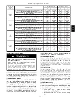
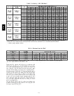
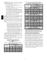
Table 7 – Electrical Data
FURNACE
MODEL
VOLTS---
HERTZ---
PHASE
OPERATING
VOLTAGE*
(VOLTS)
MAX UNIT
(AMPS)
UNIT
AMPACITY#
(AMPS)
MAX WIRE
LENGTH
}
FT. (M)
MAX FUSE/
CKT BKR
{
(AMPS)
MIN WIRE
GAGE
MAX
MIN
045---08 / 024045
115---60---1
127
104
8.1
10.9
34 (10)
15
14
070---16 / 048070
115---60---1
127
104
9.5
12.6
29 (9)
15
14
090---16 / 048090
115---60---1
127
104
10.3
13.4
27 (8)
15
14
110---20 / 060110
115---60---1
127
104
13.1
16.9
34 (10)
20
12
135---20 / 060135
115---60---1
127
104
13.1
16.9
34 (10)
20
12
* Permissible limits of the voltage range at which the unit operates satisfactorily.
# Unit ampacity = 125 percent of largest operating component’s full load amps plus 100 percent of all other potential operating components’ (EAC, humidifier,
etc.) full load amps.
{
Time---delay type is recommended.
}
Length shown is as measured 1 way along wire path between unit and service panel for maximum 2 percent voltage drop.
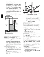
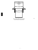
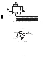
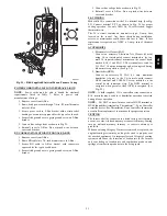
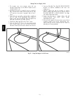
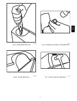
UNION
SEDI
M
ENT
TRAP
M
ANUAL
SHUTO
FF
VALVE
(REQUIRED)
GAS
SUPPLY
A02035
Fig. 22 -- Typical Gas Pipe Arrangement
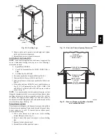
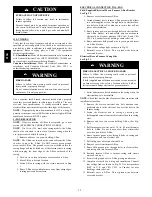
ELECTRICAL CONNECTIONS
ELECTRICAL SHOCK HAZARD
Failure to follow this warning could result in personal
injury or death
.
Blower access panel door switch opens 115--v power to
control. No component operation can occur. Do not bypass
or close switch with panel removed.
!
WARNING
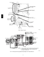
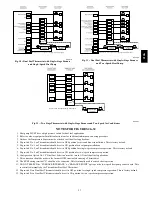
See Fig. 25 for field wiring diagram showing typical field 115--v
wiring. Check all factory and field electrical connections for
tightness.
Field--supplied wiring shall conform with the limitations of 63
_
F
(35
_
C) rise.
ELECTRICAL SHOCK AND FIRE HAZARD
Failure to follow this warning could result in personal
injury, death, or property damage.
The cabinet MUST have an uninterrupted or unbroken
ground according to NEC ANSI/NFPA 70--2008 and
Canadian Electrical Code CSA C22.1 or local codes to
minimize personal injury if an electrical fault should occur.
This may consist of electrical wire, conduit approved for
electrical ground or a listed, grounded power cord (where
permitted by local code) when installed in accordance with
existing electrical codes. Refer to the power cord
manufacturer’s ratings for proper wire gauge. Do not use
gas piping as an electrical ground.
!
WARNING
313A
Summary of Contents for 313AAV
Page 41: ...41 Table 13 Orifice Size and Manifold Pressure In wc for Gas Input Rate A08220 313A...
Page 42: ...42 Table 13 Orifice Size and Manifold Pressure In wc for Gas Input Rate CONT A08220A 313A...
Page 44: ...44 Table 14 Orifice Size And Manifold Pressure In wc For Gas Input Rate A08221 313A...