43
Technical data
and start-up
NLG5 charger
The transition into stage 2 can take place as early as phase I
1
or U
1
due to one or more conditions. In stage 2 the
voltage level U
2
is usually larger and the current level I
2
is usually smaller than in stage 1. This stage is referred to
as
Equalisation Charge
.
The transition to stage 3 then takes place when one or more requirements are fulfilled. In stage 3 both the voltage
level U
3
and the current level I
3
are usually smaller than in stage 1. This stage is referred to as
Trickle Charging
.
Further information on the conditions (parameters) can be found in chapter
8.2.7 Charging Profile Parameters
6.13.2 Mode C (CAN controlled)
In this mode, the charger is controlled by an external BMS via the CAN. During this the charger receives all the
parameters from the BMS and adapts the charging voltage and charging current to the inputs/instructions. In this
mode there is also the possibility of editing all basic settings (e.g. activation of external battery temperature
sensors, absolute shut-down limit setting etc.) using the provided
ChargeStar
software.
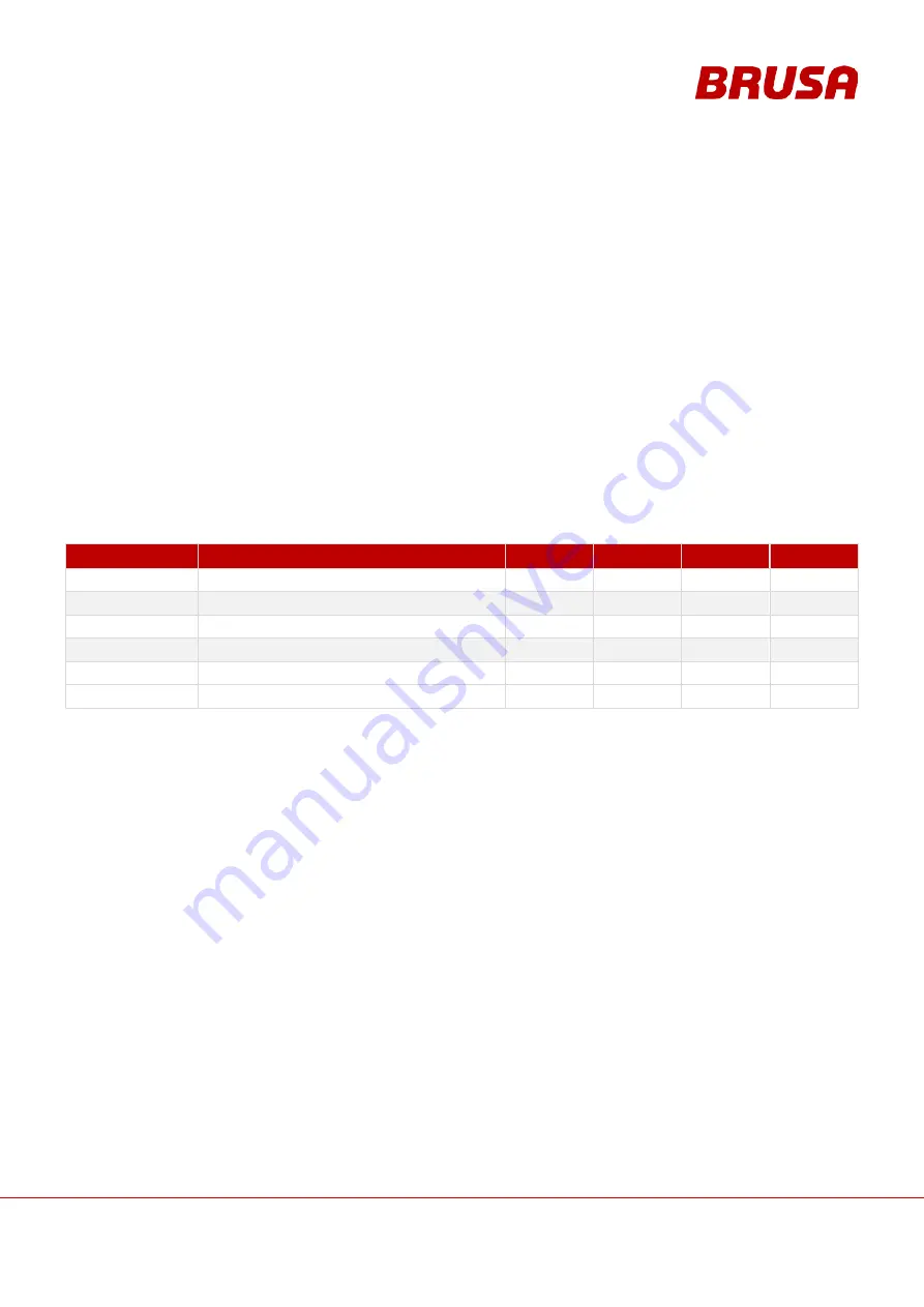
The following main signals are transmitted via the CAN *:
SIGNAL
DESCRIPTION
RX / TX
ID HEX
DLC BYTE RATE (MS)
Control
I / U target value guidelines, control bits
Rx
618 h
7
100
Status
Status of the regulator and the limiter
Tx
610 h
4
100
Int. values
I / U current values of the NLG5
Tx
611 h
8
100
Ext. values
Current external values (CP etc.)
Tx
612 h
8
100
Temp.
Internal and external temperatures
Tx
613 h
8
1000
Errors
Fault causes and warnings
Tx
614 h
5
1000
*
You can find the complete CAN matrix in the
Software
manual.


